Monday, August 30, 2010

Layout Progress Report #18 as of 08/30/2010

With the basic subroadbed in place on the upper main level and the trackwork waiting to get started,  a couple of items needed to get complete before the trackwork could start in earnest.  The first was the construction of 25 more Peco turnout machines, as was described back in Progress Report #6.  The other was the construction of some bridges for the trackwork.  I was able to knock a big dent in both of these tasks during the last week.

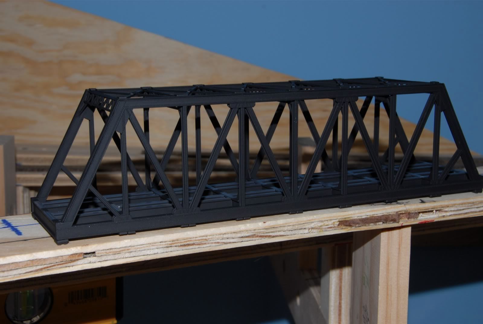
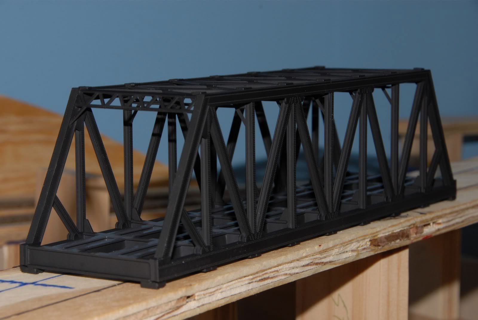
On my double-track mainline there is a 17" gap that needs to be filled with bridges.  I'm going to fill this gap with 2 bridges.  The first bridge I used will have to cross 3 tracks that will run underneath at an angle, so I had to pick a fairly long bridge.  Walthers Double-Track Truss Bridge fit the bill nicely at a length of 10-3/4".  It was built per the included instructions, and then painted with some flat black spray paint.  Some weathering is still to be done, before installation.


That leaves a 6-1/4" gap for the remaining bridge to cover.  This bridge also had to have a high clearance underneath, as the track underneath it was a little higher than the other 3 going under the other bridge.  After a fairly exhaustive search I discovered that there were no commercial kits available that fit my needs.  So either scratchbuilding or kitbashing was in order.

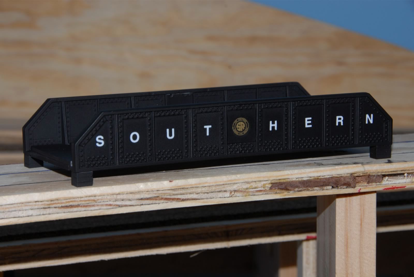
Last week as I was visiting my local crack dealer.....err hobby shop, I stumbled across the solution for my 2nd bridge as I happened to be walking thru the Hugely Oversized (HO) aisle:  Atlas HO Flatcar Girder Loads, 4 per pack.


They are a little longer than what I need, so I would have to shorten them by 3/4" as well as make a bottom for them.  Picked up some .080" styrene sheets while I was at there and set off for home to kitbash a bridge.  After some sawing, gluing. painting and decaling I had my 2nd bridge.


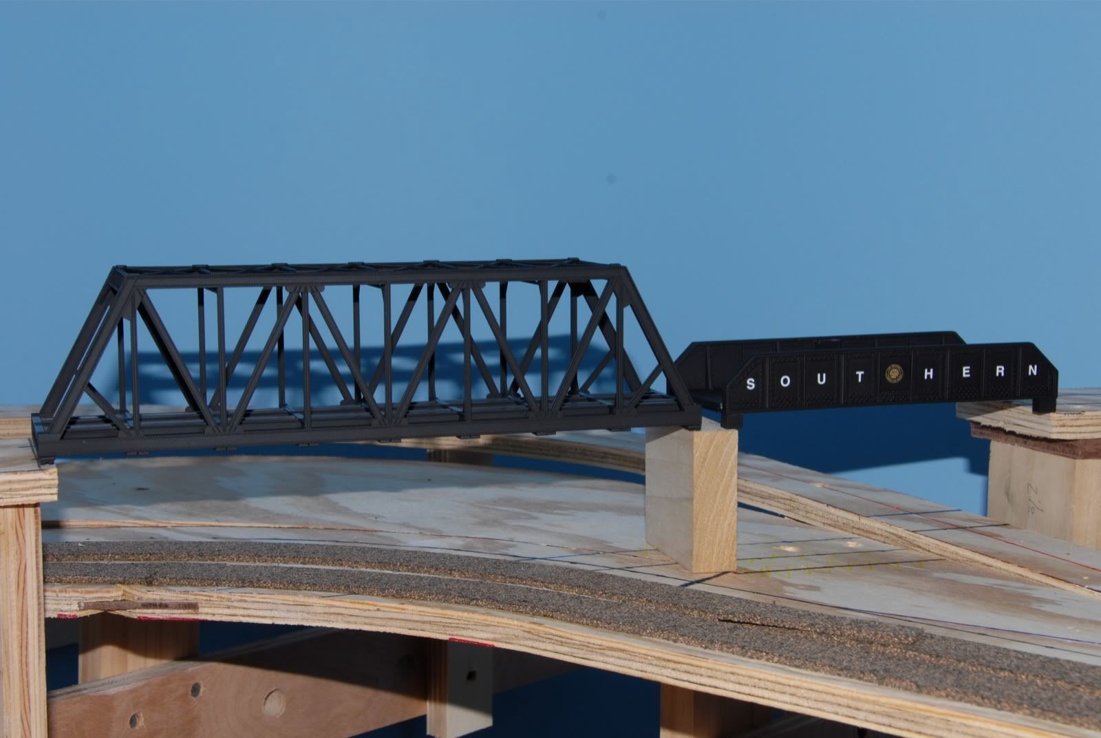
One final pic of them temporarily sitting together at the gap, giving you an idea of how they will look once they are permanently installed:


Next I will have to mount the track to them and then weather them to make them look more realistic, but they are basically ready to mount to the abutments.....oh yeah, I have to make those too!!

Oh well, the list of things to do on a Model Railroad layout is never ending.....

Sunday, August 22, 2010

Layout Progress Report #17 as of 08/22/2010

Just a quick progress report on the Cahaba Southern:  It's been a busy three weeks since the last update, and the good news is that the major benchwork on the upper main level has been completed!!  Yes, it is time to start trackwork and electrical on the main level.

In the following picture the double mainline can be seen looping above the helix.  Getting the elevations right for this loop turned out to be fairly since I had detailed elevation measurements from the trackplan.  All the elevations on the trackplan were with respect to the top of the benchwork.   I measured up the  amount of the elevations above the benchwork on the wall, and made a mark.  Next I broke out my self-leveling laser line level to match that mark.  I then held a ruler above the actual location and was able to determine the exact height of the riser by where the laser line was hitting the ruler.  After the risers were in place the wood subroadbed was cut and then put in place.  The results can be seen below:


Here is another pic a little further down the benchwork.  As you can see I have started the cork roadbed and getting ready for the track laying.  I actually had to lay the track coming from the helix to the branchline before the benchwork for the double mainline in the previous picture was put into place.


The following pic shows the some more of the complete main level benchwork.  Also, if you look closely I have mounted the front fascia for the lower staging level to give things a more finished look.  It will be painted green later on.


This picture gives you a closer look at the different mainline elevations above the helix.  Couldn't imagine doing this without a detailed trackplan with exact measurements, be it a trackplan out of a magazine or book, or one drawn up on a CAD package.


This final pic shows the rest of the cork roadbed in place on the branchline return loop.  It will more than likely be up and running before the mainlines, as those will require some bridge construction that I haven't started yet.


Until next time.........

Sunday, August 1, 2010

Layout Progress Report #16 as of 08/01/2010

As usual with most model railroads things slow down in terms of layout progress in the summer months, and the Cahaba Southern is no exception.  However, progress is still being made.  With my last post the plywood subroadbed had been cut, and since then I have been putting in risers and connecting the new subroadbed to the helix.  At this point the main lower subroadbeds are in place, and next are the remaining higher subroadbed for the double track mainline.

Here you can see the first of the subroadbed set to the appropriate height with risers, and then connected to the helix.


More subroadbed on risers in the town area of the layout.  The higher subroadbed visible in the back is not attached yet to the risers, it is just laying on them.


Here you see the subroadbed leaving the town area heading up towards the coal mine.  This picture shows the true beauty of using cookiecutter benchwork..  As the subroadbed starts to rise towards the coal mine the transiition is perfectly smooth, which will give a natural flow to the trains going up/down this transistion.  The bend of the plywood makes it perfect.


Up until this point I have been installing the risers by clamping them to the joists, leveling them to the correct height, and then screwing them to the sides of the joists.  This is tedious and takes some time. As I was getting ready to install the risers around the coal mine area I discovered that I was going to have to install some right over the wiring holes in the benchwork, effectively blocking them.  No problem, I'll just cut those to the correct height and use pocket screws to mount those to the top of the risers........

AAARRRGGGGHHH!!!  DOINK!!!  Well DUH!!  Why hadn't I thought of that before, it would have saved a lot of tedious work mounting those risers.  I have the exact rise needed from CADRail, the grid benchwork underneath is level, and I have an accurate miter saw and the pocket hole jig.... this would have saved me about a days worth of work if I had done all of the other risers that way!  Armed with my revelation I was able to knock out the remaining risers needed around the coal mine in about an hour instead of the 6-8 it would have take the other way.


I was then able to attach the subroadbed for that area.


I'm not attaching the subroadbed for the mine at this point, I'll do that afer I lay the track around the back of the layout behind the mine area.


That's all for now, next I will continue on the remaining risers for the mainline....