Saturday, November 27, 2010

Layout Progress Report #21 as of 11/27/2010

Well, the big day finally arrived on Wednesday, November 24th:  Both mainlines' track was completed and the first trains ran on them on the main level, 327 days after the first piece of benchwork went up.......Hooray!!!!  It's been a long haul so far, and the journey of this layout has a long way to go!

Here is a video showing the mainlines in operations as of this morning:


Here are some pics to look at things in more detail.  First the loops around the coal mine area:


Next the area heading into the town (one of these days I'm going to have to start naming these places)....


A further look around the town area toward where the depot will be:


Continuing further east along the layout:


Finally the loop above the helix:


After the video and above pictures were shot, I began to work on some train protectors along the hidden part of the track.  These protectors will help stop the engines and/or cars during a derailment from falling off of the roadbed on the upper level onto the lower level or, even worse, onto the floor.  With the cost of rolling stock these days it only makes sense to do this to help prevent destroying the rolling stock.  I'm only installing these on what will be the hidden track, as the visible track will have scenery around it to catch any derailments.

I'm building these with 1.5" wide strips of 1/8th inch masonite hardboard and some 1 inch corner brackets screwed to the bottom of the wooden subroadbed.  Here is a closeup that shows how it is mounted:


Here is another area showing some of the protector boards.  As you can see, the corner braces hold it in place, with a few screws here and there to secure it.  Doesn't have to be pretty, just effective:


Here is the coal mine part of the layout with all of the protector installed on that side:


Next couple of weeks things will slow down some, with the holidays approaching.  I'll work on a few odds & ends during that time, mostly some DCC stuff like installing decoders and working on routes.  However, I already have plans made for over the Christmas holidays to pick up some styrofoam sheets to start the scenery contours!!

One final video before we go.  I shot this for our friends at N Scale website, a great resource for the N Scale Model Railroader.  See y'all soon!!!


Monday, November 8, 2010

Layout Progress Report #20 as of 11/08/2010

First off let me give y'all my sincerest apologies, it's been more than a week as I had planned for my next update, it's actually been almost 2 months!!  Ouch!!! Life and priorities have gotten in the way of updating the blog, however work on the CSR has progressed nicely.

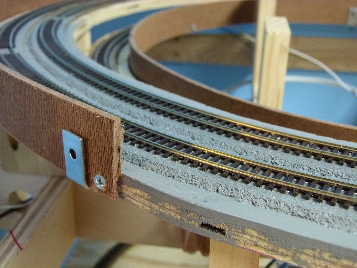
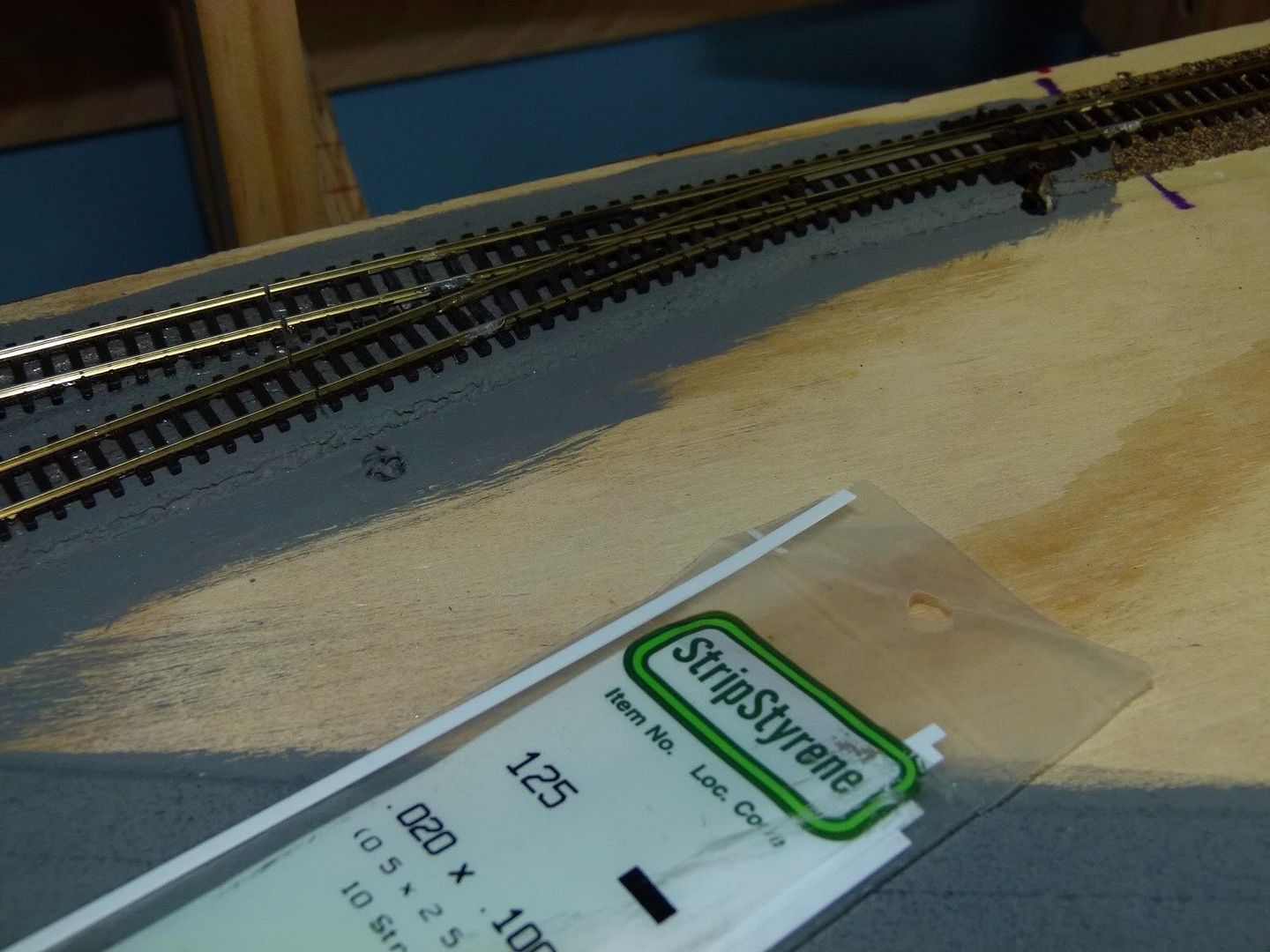
So when we last left the CSR the track had been laid for the branchline on the main level.  Next was the powering of that track, which meant the track sections had to be isolated due to reverse loops and the Peco Electrofrog turnouts that I'm using.  Using Peco Electrofrog turnouts require that the diverging sections of the turnout be insulated from the next track sections on the frog side of the turnout.  This can be done with insulating joiners when joining the track to the turnout or by cutting insulating sections into the track.  I prefer the latter, as it is much more stable and secure than insulating joiners, as they flex and deteriorate over time.

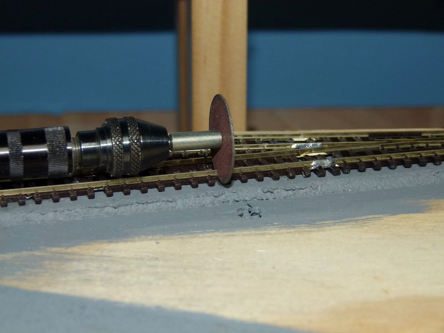
Here is the tool I use to make the insulating cuts into the track: A Dremel with a Flexshaft attachment with a #409 cutoff wheel attached.


There are other ways of making this cut including with a razor saw, however a cutoff wheel on a Dremel works best.  The flex shaft is not a necessity, however it makes it much easier to cut a nice perpendicular cut into the rail as shown in the next picture.  Note that the track on either side of the cut has been glued down, thus the rail will still be supported by the glued down track, something that would not happen if I had just used an insulated railjoiner.


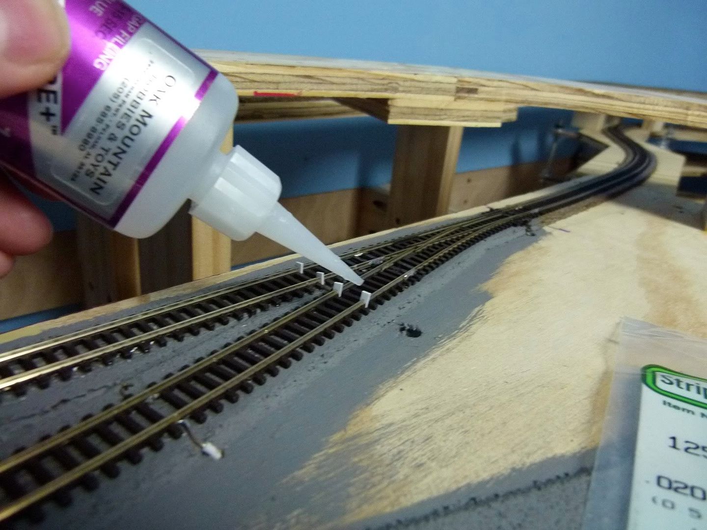
After the cut has been made I use some .020x.100 strip styrene to help insulate the gap that has been cut in the rails. The gaps can be seen in the track above the styrene.


The strip styrene is put into the gap and then cut off as shown.


After the styrene is in place some gap filling Cyanoacrylate (CA) glue is used to glue the styrene into place in the gap.


Here you can see three sets of them glued into place, waiting for the CA to dry.  I usually like to wait at least a couple of hours.  CA glue dries quickly when it is applied this, but when a whole drop is put into place it takes longer.  I also do not use an accelerator as the joint it produces will not be as strong as one without.


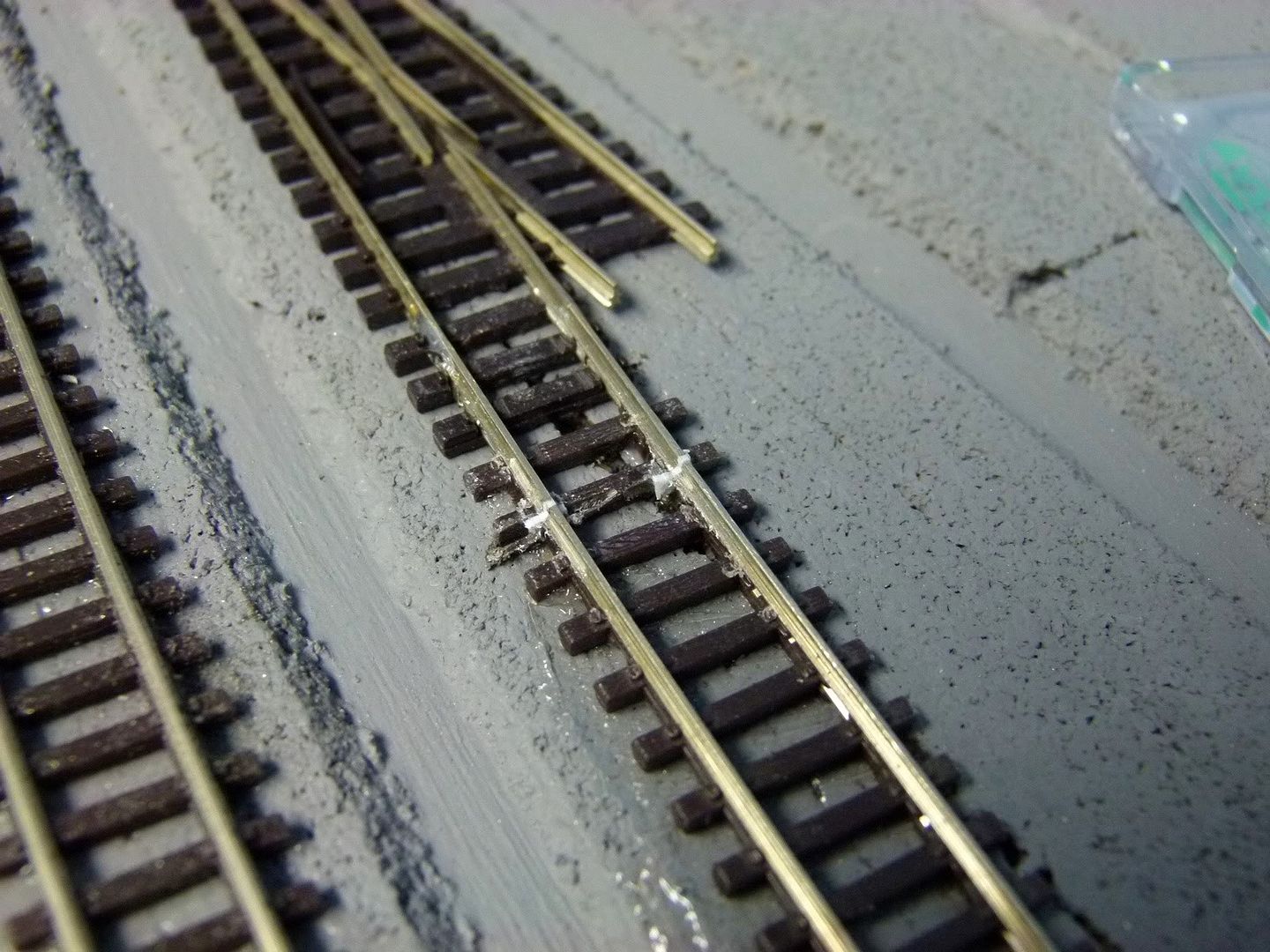
Once the glue has dried I then use a small needlefile to file the styrene into the shape of the rail.  The final result then looks like this:


Electrical feeders were attached to the flextrack before it was put in place, as shown in Progress Report #5.  Once that piece of track is in place I drill a couple of small holes next to the track and pull the feeders thru the holes as shown.


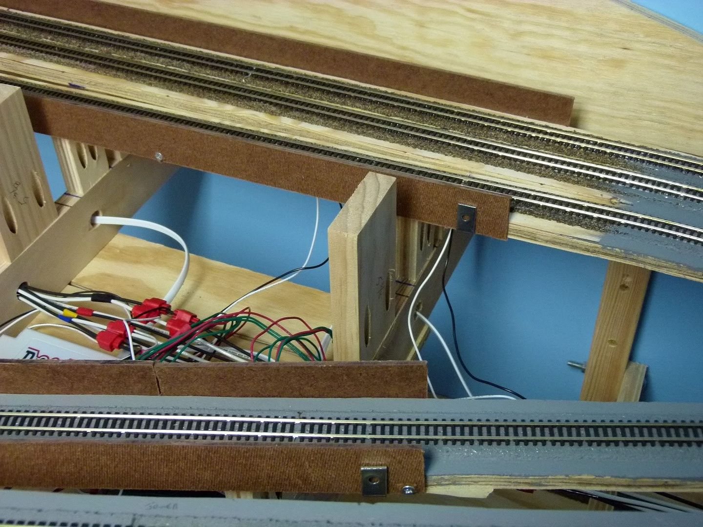
Here are the feeders shown from below the benchwork, coming thru the wooden subroadbed.


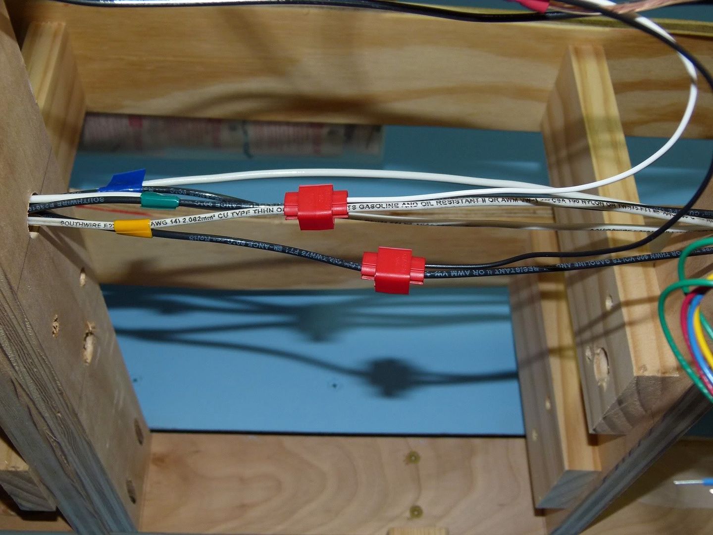
I then attach the feeders to the DCC buses underneath the layout with red 3M Scotchloks for joining the 20ga feeder to the 14ga bus wire.  Some people have had problems with intermittent connections using wiretaps like this and I have as well, but only when I was using a knockoff cheapo brand of wiretaps.  I have never had a problem with a 3M brand Scotchlok failing on me.  This is one place not to cheap out but to buy only the best name brand stuff.


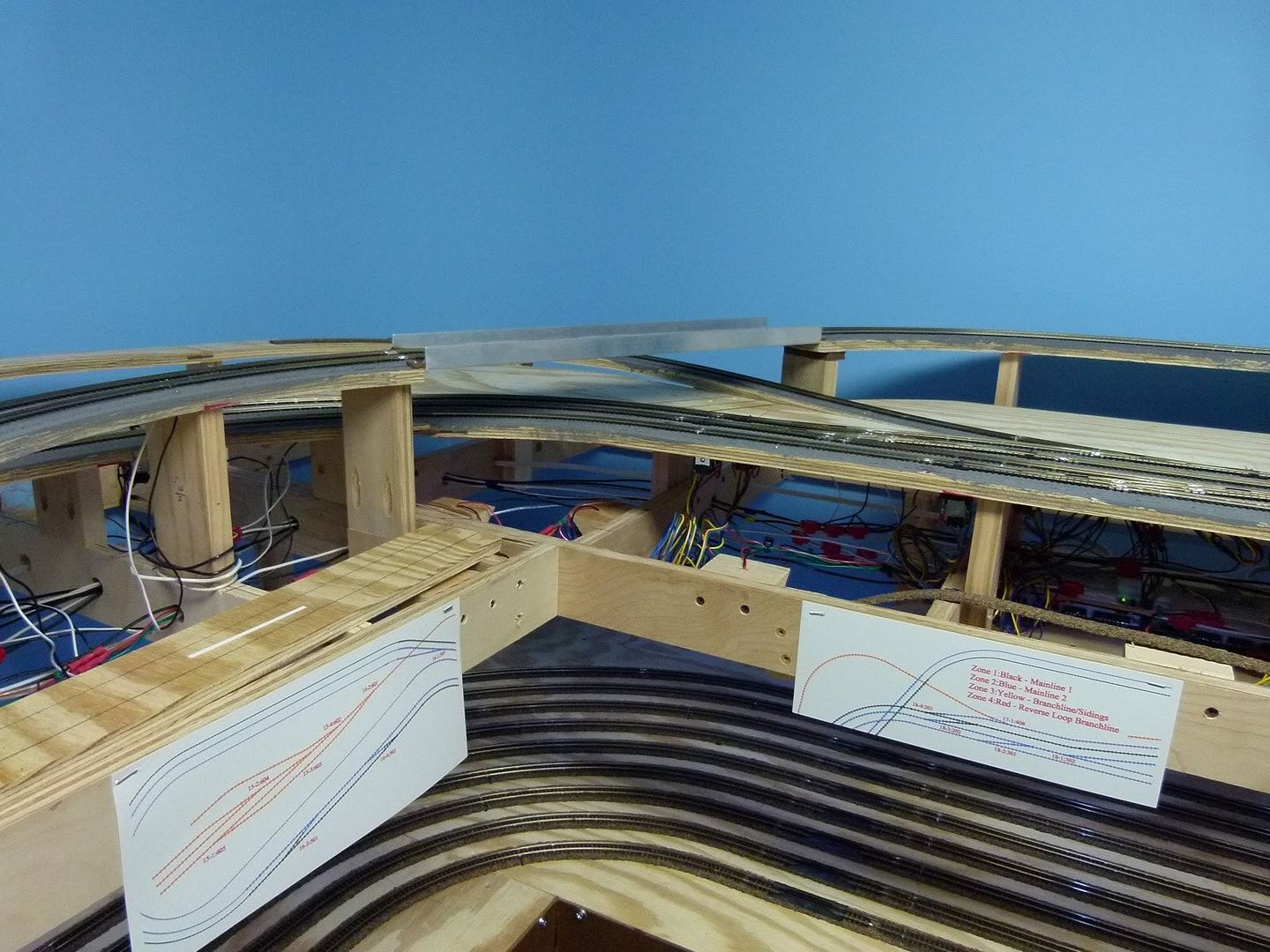
As you can see above there are 3 sets of DCC power buses running underneath this section of the layout, each of them color coded with electrical tape.  These feeders are coming from the branchline, which is being fed by the yellow DCC power bus.  Color coding and labeling things will make troubleshooting electrical issues easier, both in the present and in the future.

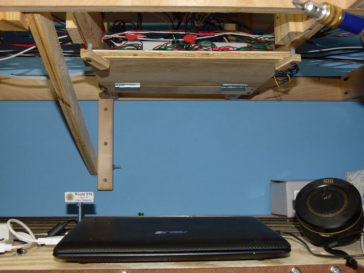
I've also put in all 6 of the Digitrax DS64 stationary decoders for the upper main level of the layout.  As I was laying track on the upper level I determined it would be easier to go ahead and have the decoders ready to power the turnout machines, attaching them as I was going along.  I used some scrap plywood and some hinges, mounting them underneath the layout in strategic locations.  Here you can see 2 sets of decoders mounted under the layout.


Here is a closeup of one of the mounting boards, with the decoders all wired up and ready to go.


The boards fold out of the way and are held in place by a couple of strips of wood attached with some spacers and screws.  Simple, cheap and effective...


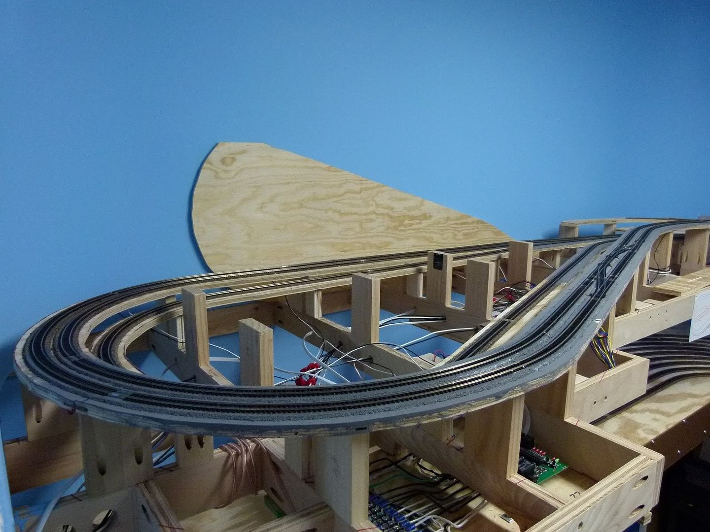
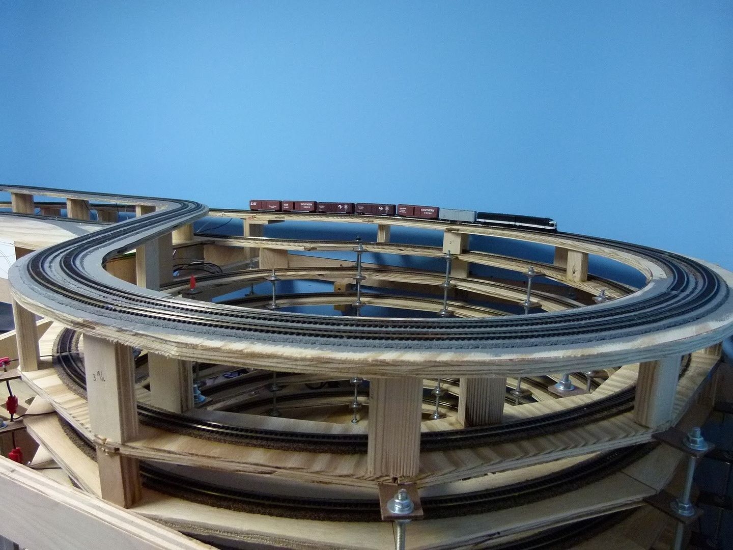
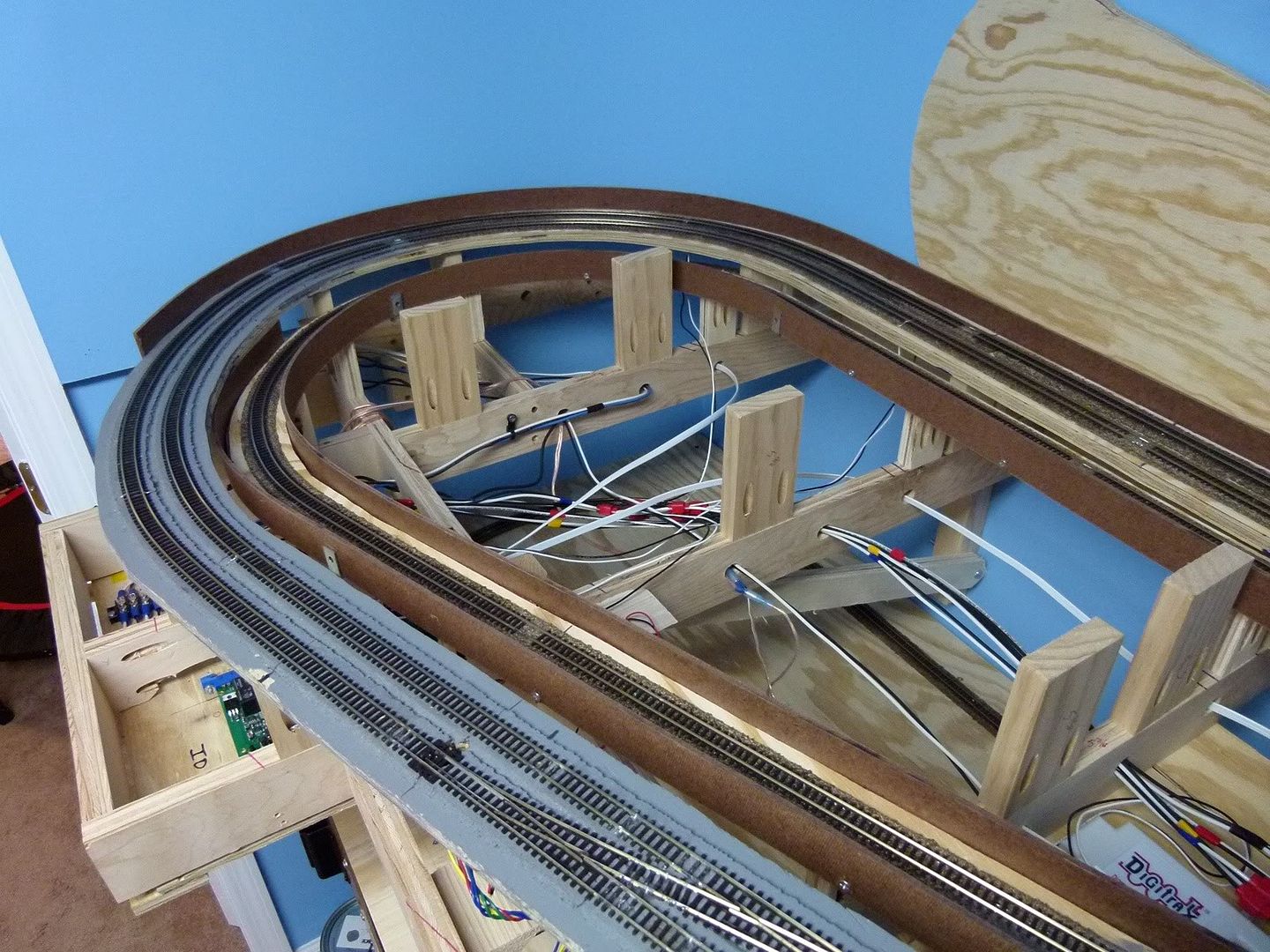
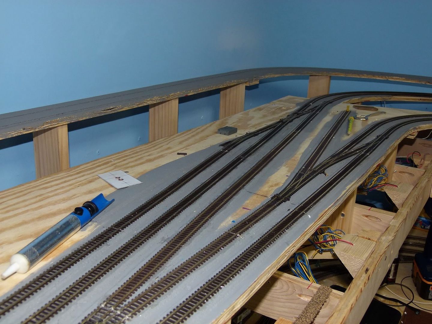
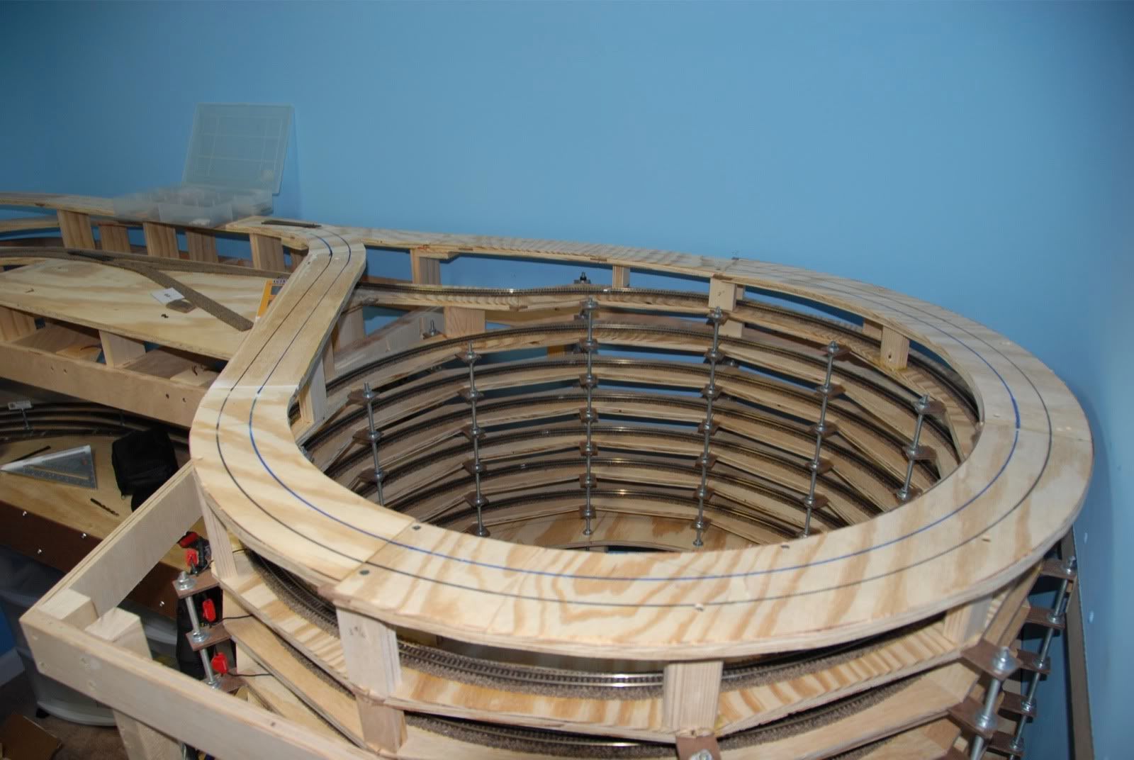
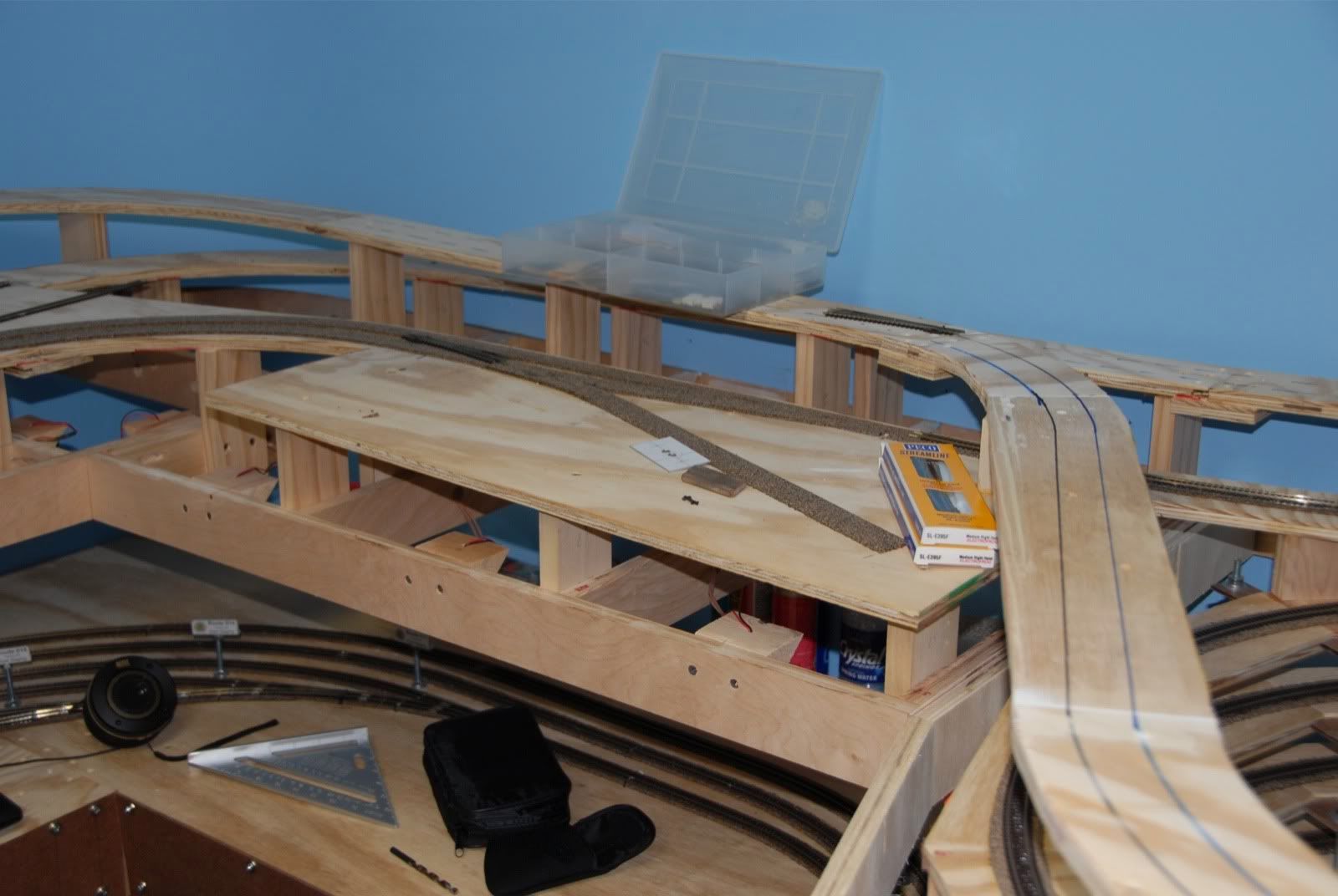
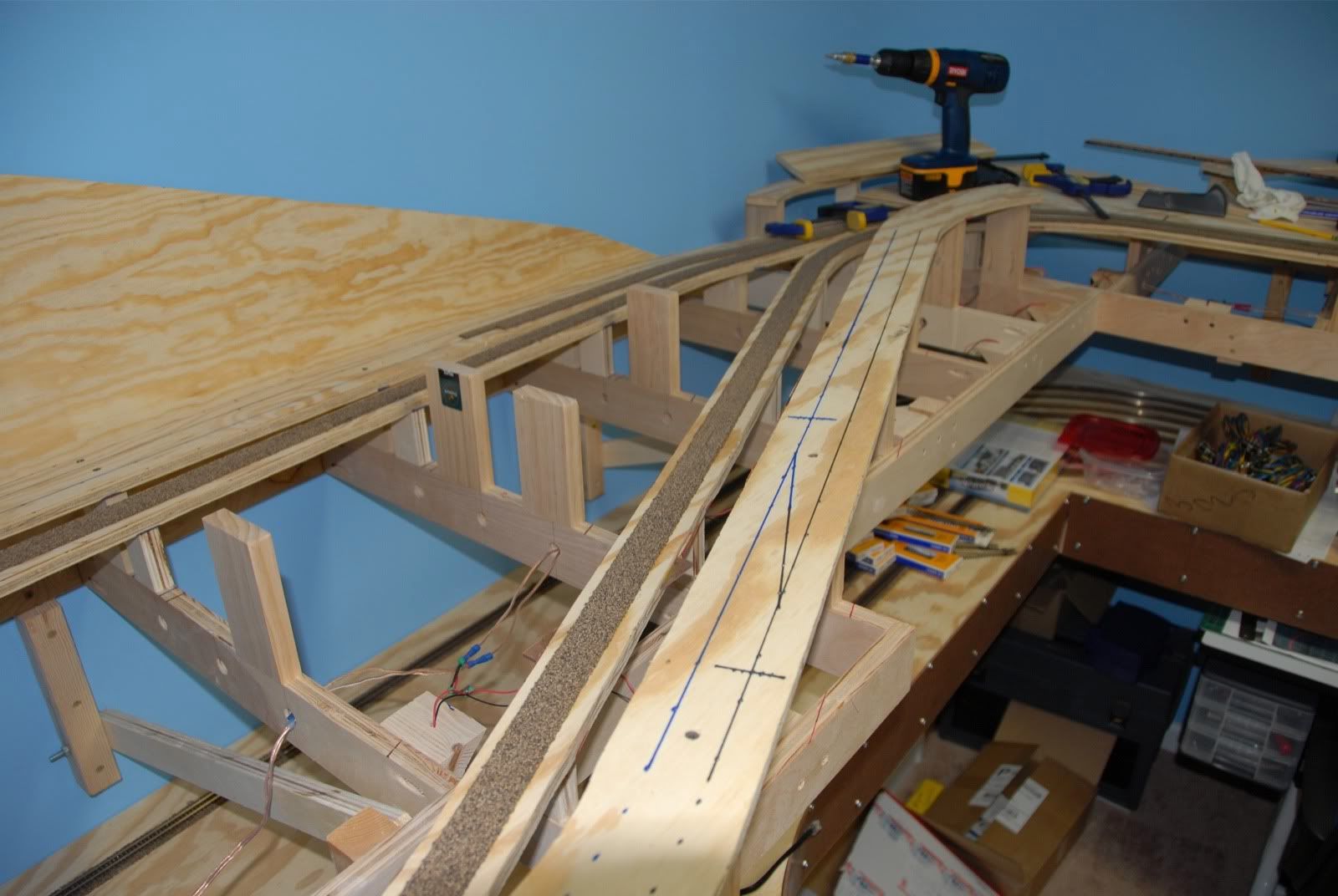
So once the decoders were in I got busy with the track laying.  All of the track in the main town area of the layout is in, with all sections powered and operational, with all turnouts operating remotely thru DCC as well.  Here is the east side of the town area, with the branchline closest to the edge, the 2 mainlines heading up and away:


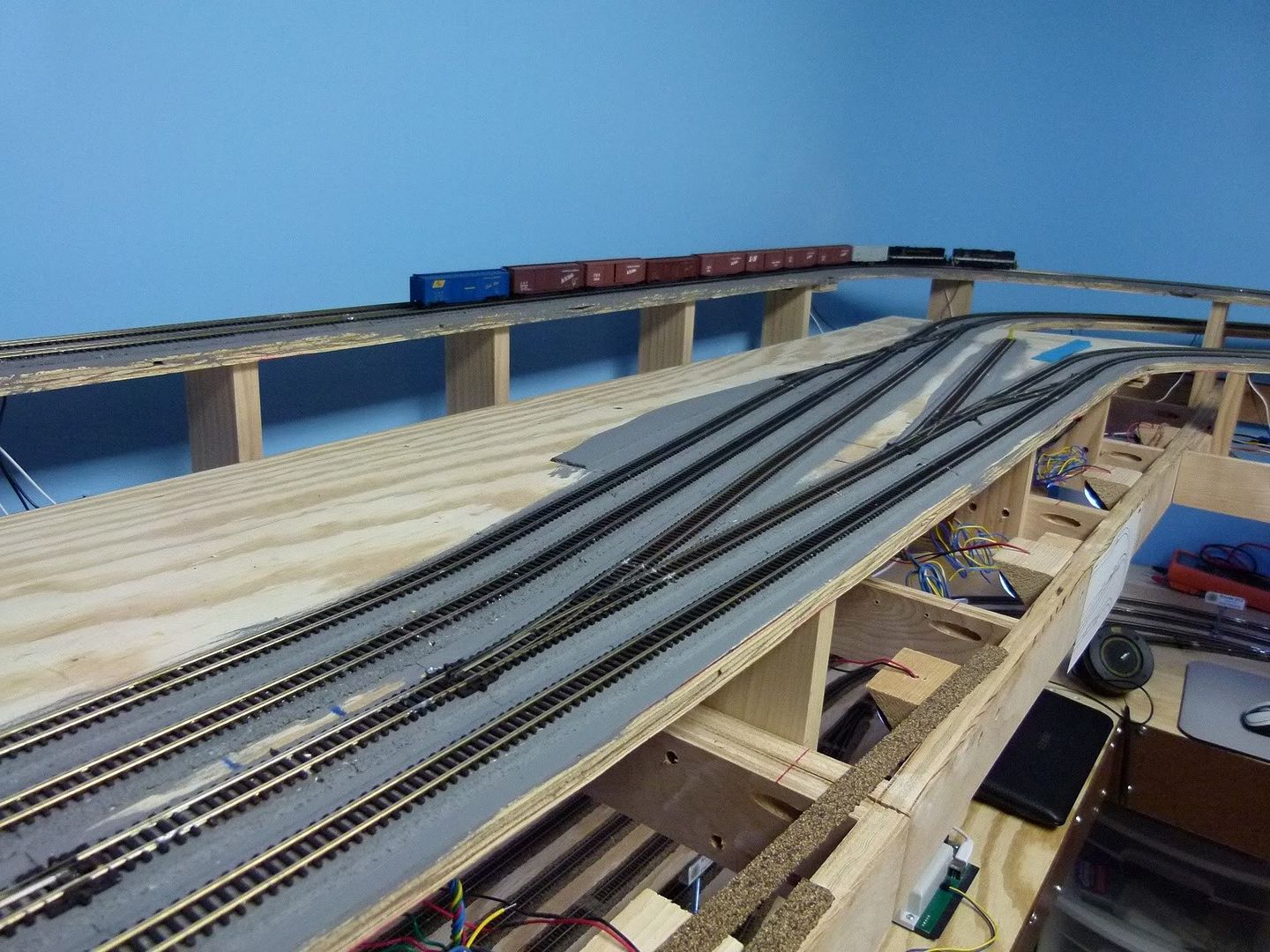
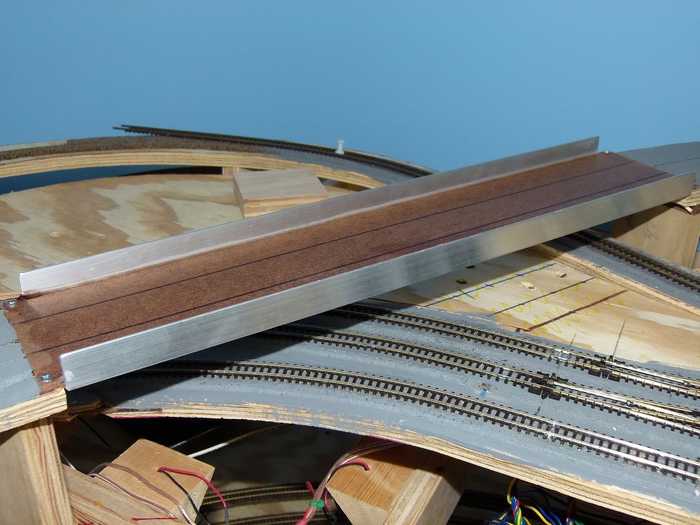
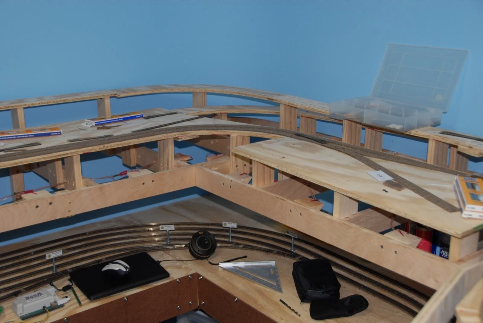
Here is the west side of the town, with the branchline once again closes to the edge, the 2 mainlines further inside, heading out underneath the temporary bridge.


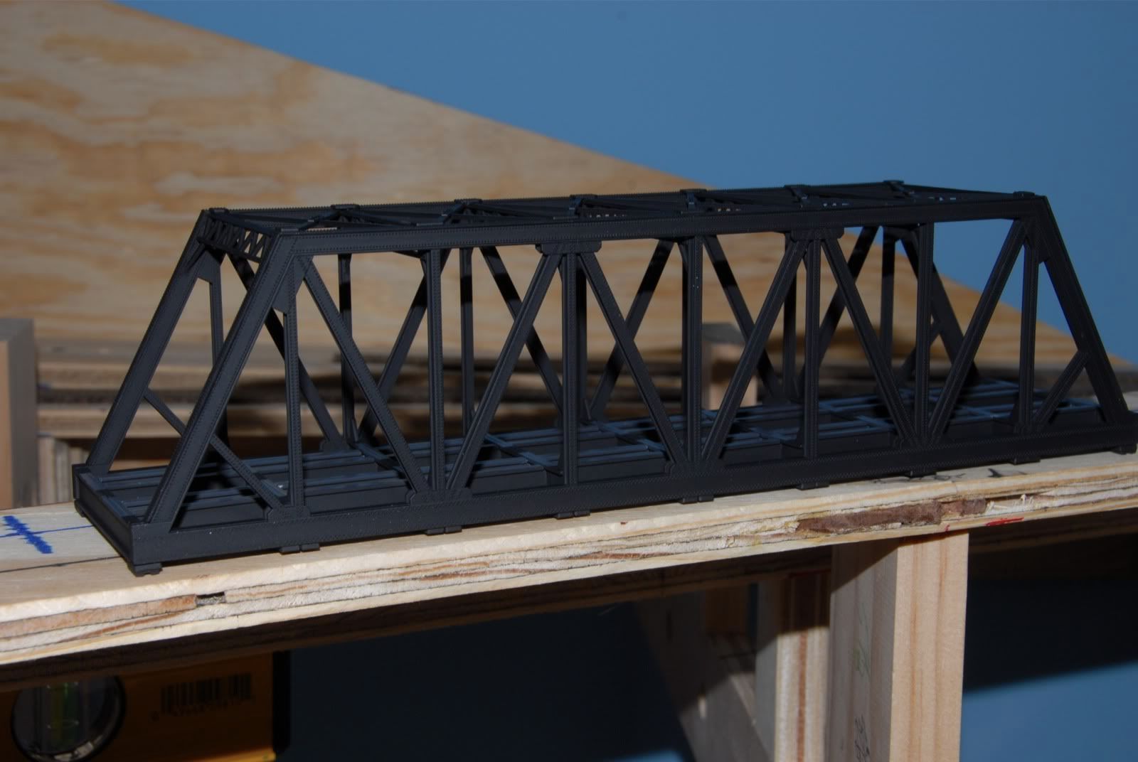
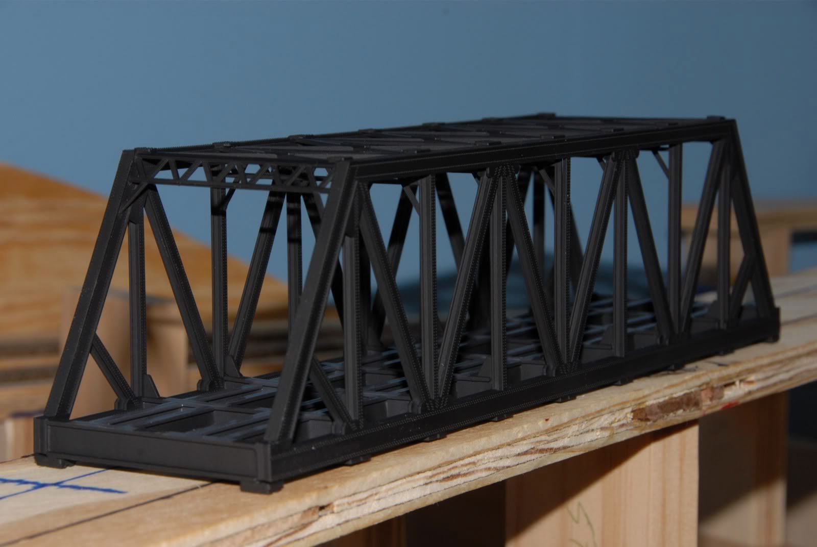
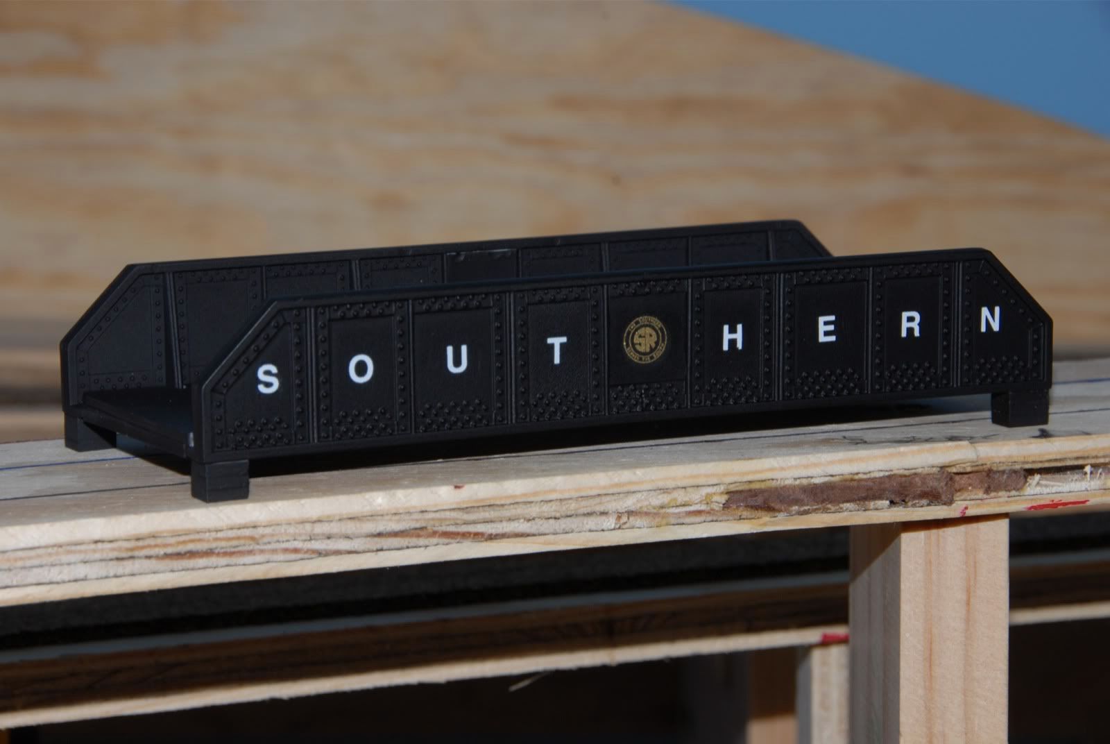
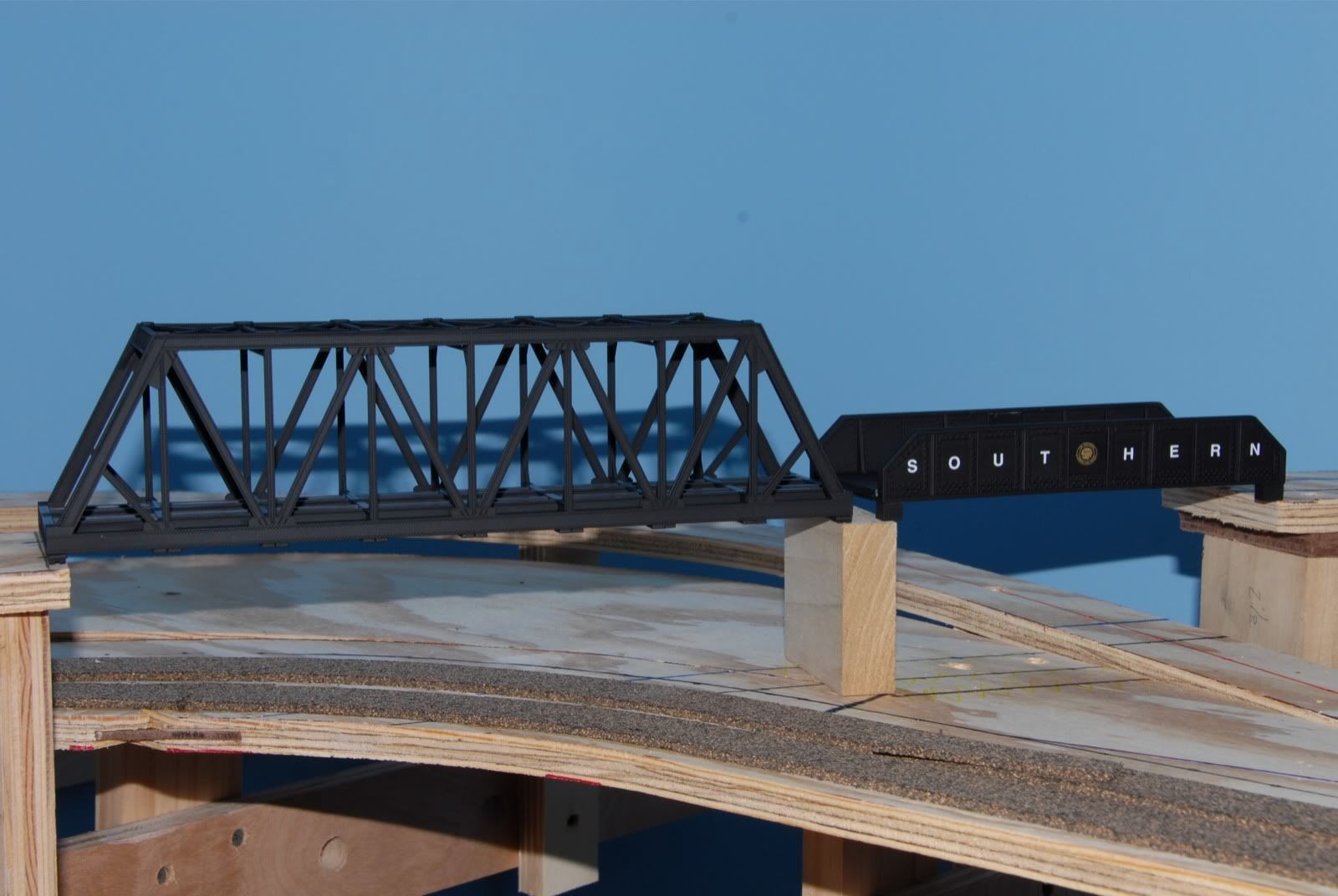
Speaking of the temporary bridge, I built it as a place holder for the 2 bridges I had shown in a previous section.  They will be put into place as the scenery progresses.  In the meantime this temporary bridge built from masonite and l-shaped aluminum glued together will be the placeholder.


Next step is to tie the mainlines together, and that day when the trains can run continuously is getting close......until next time!

Sunday, September 19, 2010

Layout Progress Report #19 as of 09/19/2010

Wow, three weeks have already gone by since my last post, and it has been a busy time on the Cahaba Southern.  I've probably put in another 40+ hours the last 3 weekends plus some weeknights, and good progress is being made.  Here is what it typically looks like while all the work is going on, tools and other needed stuff everywhere:


In order to put in the bridges I had built in the last progress report I need to get all the trackwork in place that the bridges will pass over.  However, nn order to put in the trackwork I needed to get the power buses and main distribution panel put in.  So, it's time to pull a bunch of wire and connect a bunch of connectors, and after a good days of work later it looks like this:


The upper main level will be subdivided into 4 districts:  the 2 main lines, the branchline and industries, and the reversing loop.  I have a 2nd feed coming off of the DCS200 to supply the main level, and it goes to the PM42 distribution panel shown on the bottom right.  The AR1 for the reversing loop is mounted above it.  The 4 district bus wires are run through the layout, with each pair coded with different colors of electrical tape to help distinguish it.  These bus wires can be seen leaving the distribution on the left.  Everything is mounted and hinged to the bottom of the main level and can swing down for maintenance access.

So now that I have power, it is time to lay some track......or is it?  Well, almost, one more thing to get done before the track get put down.  In another previous progress report I showed the PL-10 switch machines from Peco and the mounts and wiring needed for them.  These have to be put in and mounted as the turnouts are laid.  So I spend a long afternoon preassembling my switch machines, and here is a pic of some mounted to the main level:


Well, if there are mounted switch machines that must mean that some turnouts and track has been laid...


...and there it is.  This pic shows the branchline track coming up from the helix.  Note that I've also painted the cork roadbed before putting down the track.  I paint my cork roadbed ballast color, and then lay the track attaching it with clear adhesive caulk. Then when I later ballast it it will require less ballast to make it look right as you don't necessarily have to cover as thick. It also helps around turnouts, as ballasting there is a frequent source of problems. Not having to use as much ballast and glue around the turnouts can help prevent problems.

After coming around the bend the branchline is heading into town:


The 2 mainlines are to the outside of the branchline and are not in place yet.  Here is another pic of the branchline as it heads towards where the bridges will be:


One final pic of the branchline reverse loop as it sits underneath where the coalmine will be.  Where the mainlines will go can be seen around the outside of the branchline:


So the track for the branchline is down, however the feeders have not been connected to the main power buses nor have the insulating gaps been cut into place.  Once that is done I will be able to run a train continuously from the lower staging to the upper branchline and back again.  For now, I'm pooped, so I'm saving that for next week. Until then!!!

Monday, August 30, 2010

Layout Progress Report #18 as of 08/30/2010

With the basic subroadbed in place on the upper main level and the trackwork waiting to get started,  a couple of items needed to get complete before the trackwork could start in earnest.  The first was the construction of 25 more Peco turnout machines, as was described back in Progress Report #6.  The other was the construction of some bridges for the trackwork.  I was able to knock a big dent in both of these tasks during the last week.

On my double-track mainline there is a 17" gap that needs to be filled with bridges.  I'm going to fill this gap with 2 bridges.  The first bridge I used will have to cross 3 tracks that will run underneath at an angle, so I had to pick a fairly long bridge.  Walthers Double-Track Truss Bridge fit the bill nicely at a length of 10-3/4".  It was built per the included instructions, and then painted with some flat black spray paint.  Some weathering is still to be done, before installation.


That leaves a 6-1/4" gap for the remaining bridge to cover.  This bridge also had to have a high clearance underneath, as the track underneath it was a little higher than the other 3 going under the other bridge.  After a fairly exhaustive search I discovered that there were no commercial kits available that fit my needs.  So either scratchbuilding or kitbashing was in order.

Last week as I was visiting my local crack dealer.....err hobby shop, I stumbled across the solution for my 2nd bridge as I happened to be walking thru the Hugely Oversized (HO) aisle:  Atlas HO Flatcar Girder Loads, 4 per pack.


They are a little longer than what I need, so I would have to shorten them by 3/4" as well as make a bottom for them.  Picked up some .080" styrene sheets while I was at there and set off for home to kitbash a bridge.  After some sawing, gluing. painting and decaling I had my 2nd bridge.


One final pic of them temporarily sitting together at the gap, giving you an idea of how they will look once they are permanently installed:


Next I will have to mount the track to them and then weather them to make them look more realistic, but they are basically ready to mount to the abutments.....oh yeah, I have to make those too!!

Oh well, the list of things to do on a Model Railroad layout is never ending.....

Sunday, August 22, 2010

Layout Progress Report #17 as of 08/22/2010

Just a quick progress report on the Cahaba Southern:  It's been a busy three weeks since the last update, and the good news is that the major benchwork on the upper main level has been completed!!  Yes, it is time to start trackwork and electrical on the main level.

In the following picture the double mainline can be seen looping above the helix.  Getting the elevations right for this loop turned out to be fairly since I had detailed elevation measurements from the trackplan.  All the elevations on the trackplan were with respect to the top of the benchwork.   I measured up the  amount of the elevations above the benchwork on the wall, and made a mark.  Next I broke out my self-leveling laser line level to match that mark.  I then held a ruler above the actual location and was able to determine the exact height of the riser by where the laser line was hitting the ruler.  After the risers were in place the wood subroadbed was cut and then put in place.  The results can be seen below:


Here is another pic a little further down the benchwork.  As you can see I have started the cork roadbed and getting ready for the track laying.  I actually had to lay the track coming from the helix to the branchline before the benchwork for the double mainline in the previous picture was put into place.


The following pic shows the some more of the complete main level benchwork.  Also, if you look closely I have mounted the front fascia for the lower staging level to give things a more finished look.  It will be painted green later on.


This picture gives you a closer look at the different mainline elevations above the helix.  Couldn't imagine doing this without a detailed trackplan with exact measurements, be it a trackplan out of a magazine or book, or one drawn up on a CAD package.


This final pic shows the rest of the cork roadbed in place on the branchline return loop.  It will more than likely be up and running before the mainlines, as those will require some bridge construction that I haven't started yet.


Until next time.........

Sunday, August 1, 2010

Layout Progress Report #16 as of 08/01/2010

As usual with most model railroads things slow down in terms of layout progress in the summer months, and the Cahaba Southern is no exception.  However, progress is still being made.  With my last post the plywood subroadbed had been cut, and since then I have been putting in risers and connecting the new subroadbed to the helix.  At this point the main lower subroadbeds are in place, and next are the remaining higher subroadbed for the double track mainline.

Here you can see the first of the subroadbed set to the appropriate height with risers, and then connected to the helix.


More subroadbed on risers in the town area of the layout.  The higher subroadbed visible in the back is not attached yet to the risers, it is just laying on them.


Here you see the subroadbed leaving the town area heading up towards the coal mine.  This picture shows the true beauty of using cookiecutter benchwork..  As the subroadbed starts to rise towards the coal mine the transiition is perfectly smooth, which will give a natural flow to the trains going up/down this transistion.  The bend of the plywood makes it perfect.


Up until this point I have been installing the risers by clamping them to the joists, leveling them to the correct height, and then screwing them to the sides of the joists.  This is tedious and takes some time. As I was getting ready to install the risers around the coal mine area I discovered that I was going to have to install some right over the wiring holes in the benchwork, effectively blocking them.  No problem, I'll just cut those to the correct height and use pocket screws to mount those to the top of the risers........

AAARRRGGGGHHH!!!  DOINK!!!  Well DUH!!  Why hadn't I thought of that before, it would have saved a lot of tedious work mounting those risers.  I have the exact rise needed from CADRail, the grid benchwork underneath is level, and I have an accurate miter saw and the pocket hole jig.... this would have saved me about a days worth of work if I had done all of the other risers that way!  Armed with my revelation I was able to knock out the remaining risers needed around the coal mine in about an hour instead of the 6-8 it would have take the other way.


I was then able to attach the subroadbed for that area.


I'm not attaching the subroadbed for the mine at this point, I'll do that afer I lay the track around the back of the layout behind the mine area.


That's all for now, next I will continue on the remaining risers for the mainline....

Sunday, June 27, 2010

Layout Progress Report #15 as of 06/27/2010

Wow, hard to believe it's been over 6 weeks since I last posted an update!  Things have been really busy, and the CSR took a backseat to other commitments.  I did get a chance to attend the Southeastern Region NMRA convention.  If you've never attended a regional or national NMRA convention, I highly recommend it.  

Back to the CSR, I've started working on the wooden subroadbed the last couple of weekends.  I'm using cookie cutter roadbed, using similar techniques as in Progress Report #3.  I'm once again using 1/2" plywood for the subroadbed.  I cut the plywood to the size of the benchwork underneath.  Next I print out a 1-to-1 scale layout diagram and attach it to the plywood.  The diagram also had lines on it for the subroadbed.  These will provide the cutting guides for the jigsaw.


I then once again used a center punch and multiple color Sharpies to mark all the lines.  Next I carried the plywood pieces to the garage to cut them in to cookie-cutter pieces with the jigsaw.


After a hour or so of sawing the roadbed was cut and then placed back onto the layout.


Next it will be time to start putting in risers underneath the plywood.  Until then.....