Sunday, April 25, 2010

Layout Progress Report #13 as of 04/25/2010

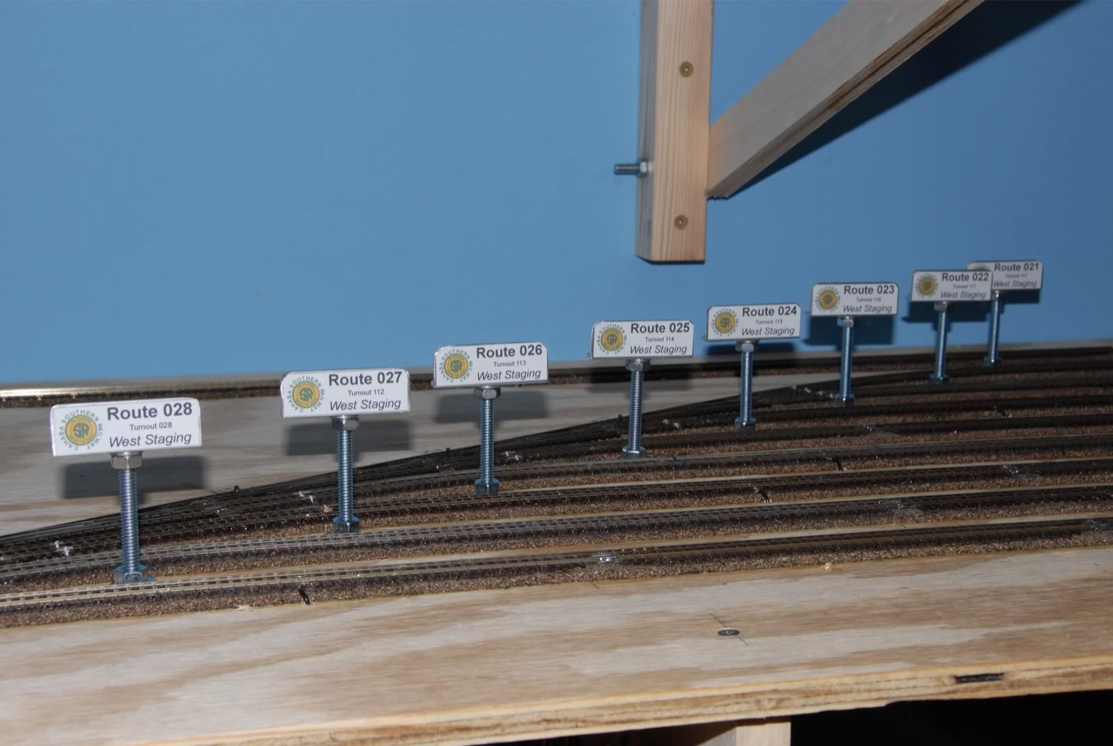
Getting ready to start on the upper level backdrop, so I'm trying to knockout a few odds & ends on the lower level.  I plan on adding some control panels to the front fascia at a later time, however I wanted to do was add some kind of visual indicator directly to the yard itself that shows when the train has cleared the switch as well as which turnout route is programmed for which yard track.

Here is what I came up with:


The routing boards are made from aluminum L-stock, some bolts, washers, and attached to a T-nut mounted to the bottom of the plywood.  I purchase the aluminum at a local hardware store.  Cut it down to a 2 inch piece with a hacksaw, and then smoothed out the corners with a tabletop grinder and file to eliminate any sharp edges.  I then drilled a 1/4" hole into the aluminum to mount the 3" bolt.


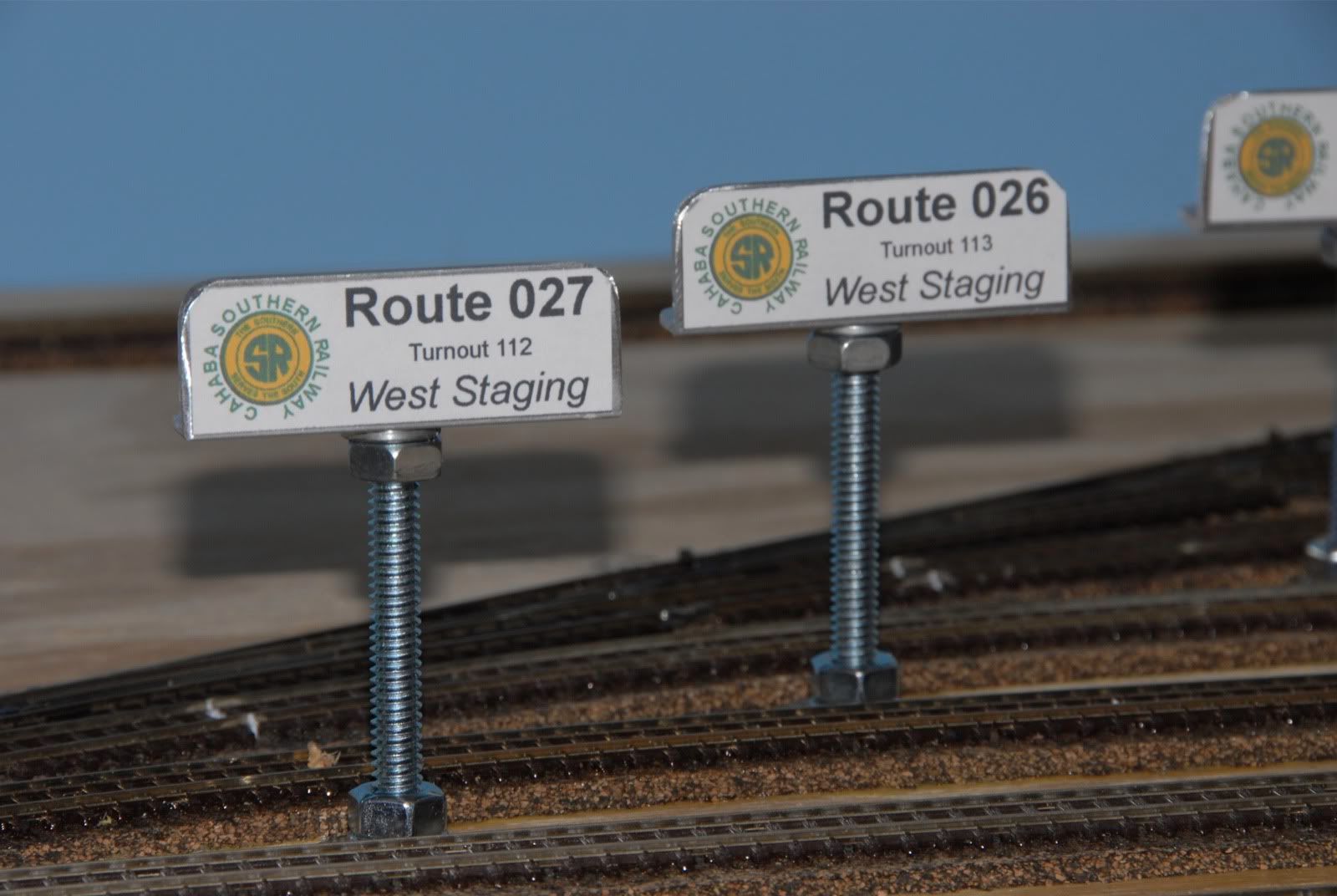
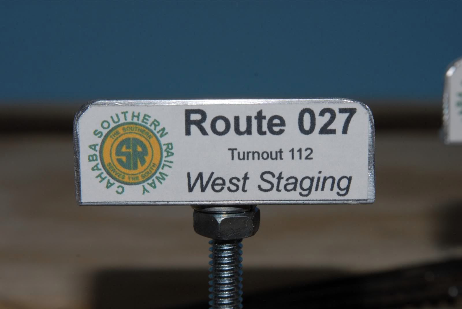
Here's a close up pic of the completed routing board assembly.  The route shown is what is programmed into the Digitrax DS64, allowing the yard operator to direct the train by throwing one switch address on the controller


The final touch was done on my inkjet with some label paper.  It shows the Cahaba Southern logo for the first time.


Still trying the figure out the best thing to do for lighting the lower level.  Hope to have some progress on that next time.......

Sunday, April 18, 2010

Layout Progress Report #12 as of 04/18/2010

It's been a busy couple of days on the Cahaba Southern, as the upper main level benchwork was started and completed.  Most of the major wood cutting work had been done several months ago when the lower level was made.  At this point all that needed to be done is for the beams to be cut to length and a few pocket holes to be drilled, as the cross-members were ready to go.  The other part that required some work is the benchwork around the helix, as it required some angled cuts and some fitting around the helix itself.

The first piece of framework is mounted to the walls.  As can be seen in the picture support blocks have been put in place around the walls to help support the framework.  In addition to these blocks which are mounted to the wall studs the framework is attached to the wall studs as well with 3 inch screws.


The second piece of framework is completed and mounted.  It is secured to the wall, the first piece of framework,  and the framework around the helix.


The following picture shows the helix framework in a little more detail.  3 of the outside helix support rods had to be shortened as they were in the way of the framework.  Small wooden spacers were cut to support the helix at those points where the rods were shortened.  I'm sorry that I didn't take any pictures as I was doing this, as I plain forgot too since I was so busy figuring out these adjustments!  Sometimes even the most well-thought out plans require last minute tweaks....


The third piece of framework is in place.


Then the fourth and final piece of framework is installed.


That went quick!!  I guess after the weeks of working on the helix there was some renewed energy to work on the Cahaba Southern again.  Next it will be time to work on the curved backdrop for the main level, as well, as getting some lighting in place for the staging level.  Until then.......
Tuesday, April 13, 2010

Layout Progress Report #11 as of 04/13/2010

It is finished!!! It took some time, got sidetracked with some other obligations, but the helix is finally complete. Here it is in all it's glory:


Here is a pic taken at a wider angle, showing how it fits into the benchwork:


6 and 2/3rds total loops, each one gaining 2.5". It comes out 2 5/8" above the main level benchwork. After I get my shoulder popped back into it's socket from patting myself on my back, it will be time to start building the main level framework. You can see how high it will be based upon the two strips I've already mounted behind the helix on the walls. 


Sawdust Making Part II will start this Friday!

Sunday, April 4, 2010

How-To: Laying & Joining Flextrack in a Curve

Laying and joining flextrack on curves is something that can be daunting and frustrating for beginners as well as experienced model railroaders alike, but here is the technique that has served me well over the years. The following pic shows a piece of Peco 55 flextrack in place on a 17" radius curve on my helix, waiting for the next piece. First things first is always put the movable rail on the inside of the track.
When putting the movable rail on the inside that inside rail will end up being longer.
Using a cutting tool (in my case a Dremel with flexshaft and cutoff wheel) I then trim the inside rail to match the length of the outside rail. You can see the red mark of where to cut the rail.

After the first piece is trimmed to length I lay the second piece out, movable rail on the inside, with a radius close to the final one.

Now the second piece needs trimming on the inside rail.

Once the second piece is trimmed, attach the two rails together with rail joiners.

Next solder the 2 pieces of flex to each other and the joiners.

Here is the soldered rail.


A little cleaning up along the top edge and inside edge with a needle file to remove any stray burrs, giving a perfectly smooth joint.

Now pull the track out of the way towards the inside and put down the adhesive latex caulk to hold the new piece of track.

Smooth out the caulk and set the new flextrack piece in place, tapping in some thumbtacks to help hold it. The caulk will turn clear when dry.

All done, or as in my case: Lather, Rinse, Repeat!!!