Sunday, January 31, 2010

Layout Progress Report #6 as of 01/31/2010

Progress on the Cahaba Southern is steady, with more trackwork going on.  All the turnouts are in place for the lower level, with all undertable switch machines mounted, wire prepped, and tested.  I'm using Peco PL-10 switch machines on the Cahaba Southern, with Peco PL-13 Accessory switches mounted for future control panel indication purposes.  Final control of the turnouts will fall to Digitrax DS64 stationary decoders.  Here's what it took to get them installed:

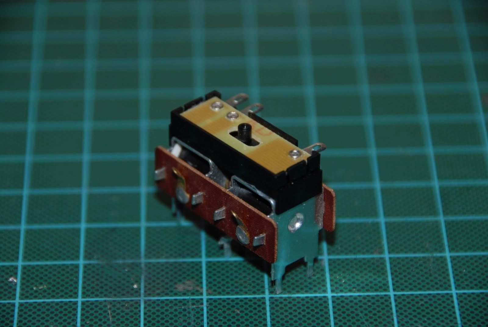
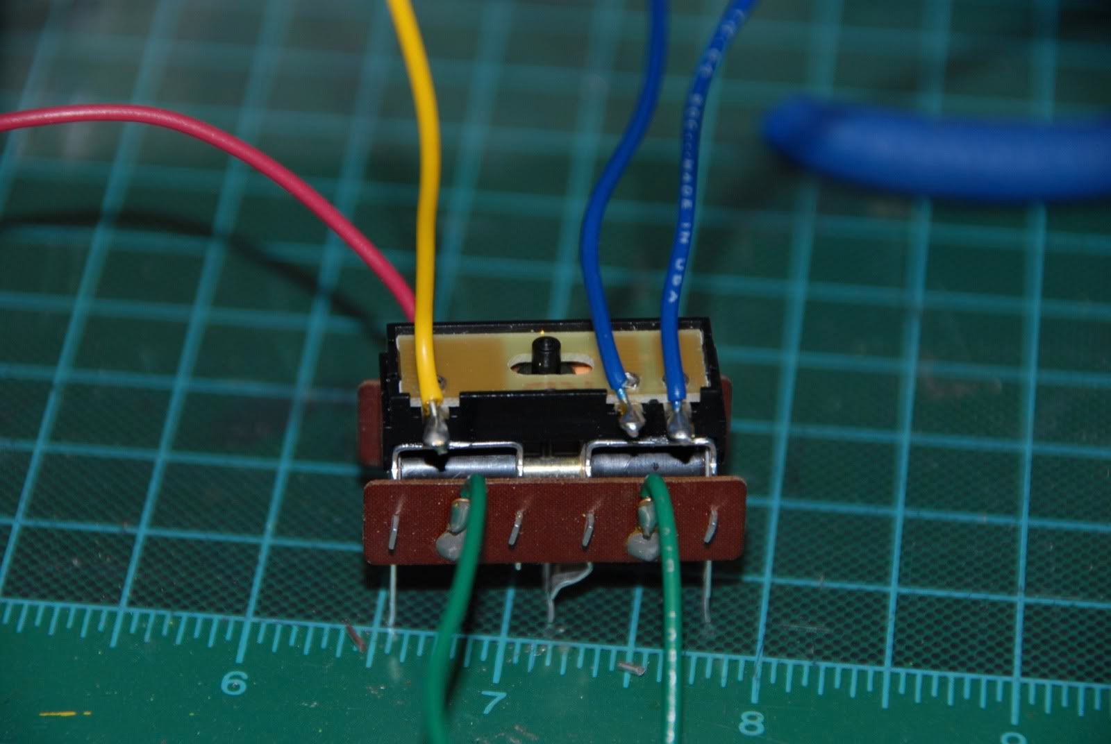
First. mount the PL-13 to the PL-10 with some adhesive.  I used silicone sealant for this.  Let them sit for overnight for the silicone to dry.


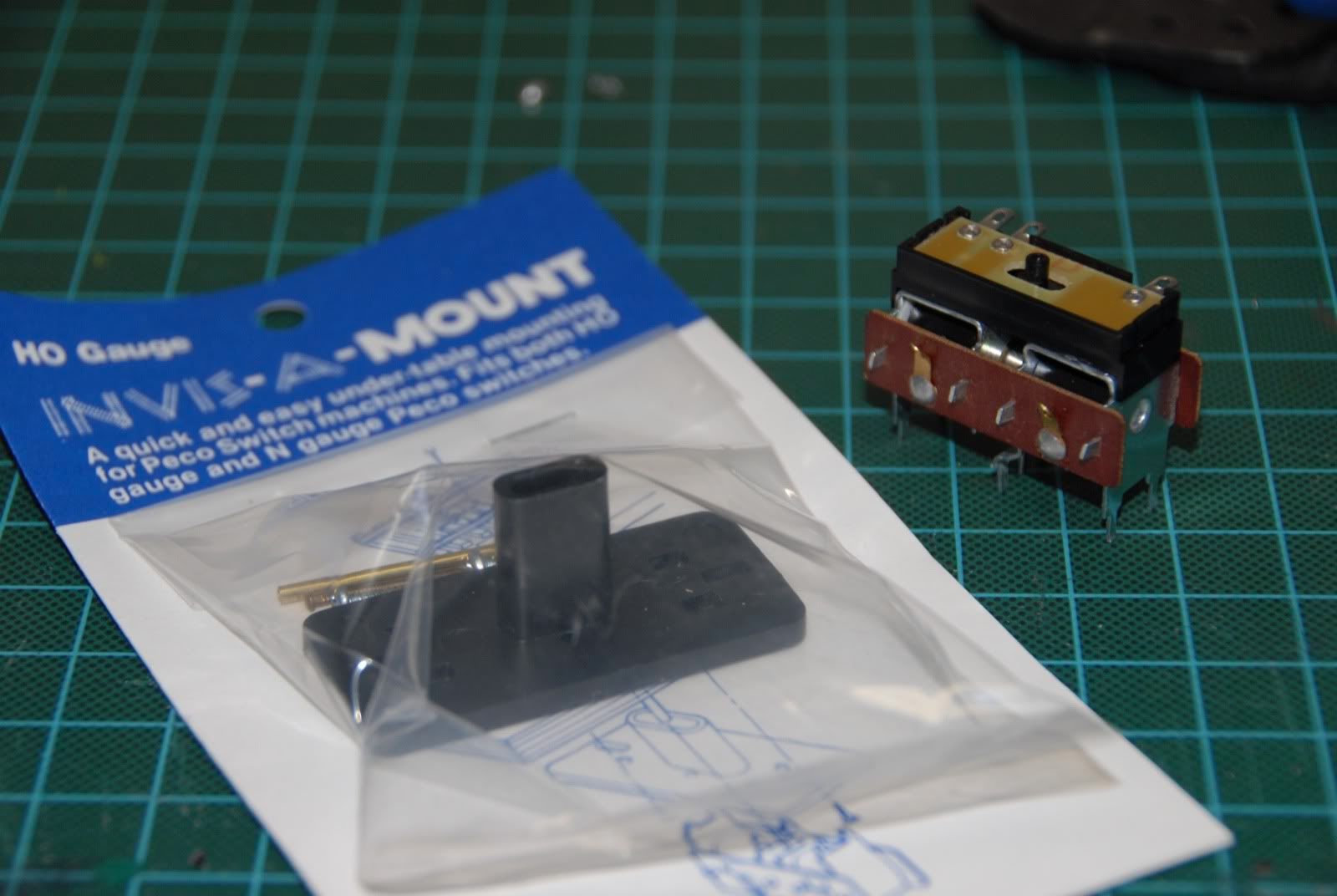
I'm using Invis-A-Mount undertable mounts for mounting the Peco PL-10s.  I did not want to mount the PL-10s directly to the turnouts, as they require a large hole in the roadbed to mount.  Using the mounts made it easier to mount with a much smaller hole required in the layout.  They are made by F&H Enterprises, but I believe they are out of business.  However they can still be found on ebay.


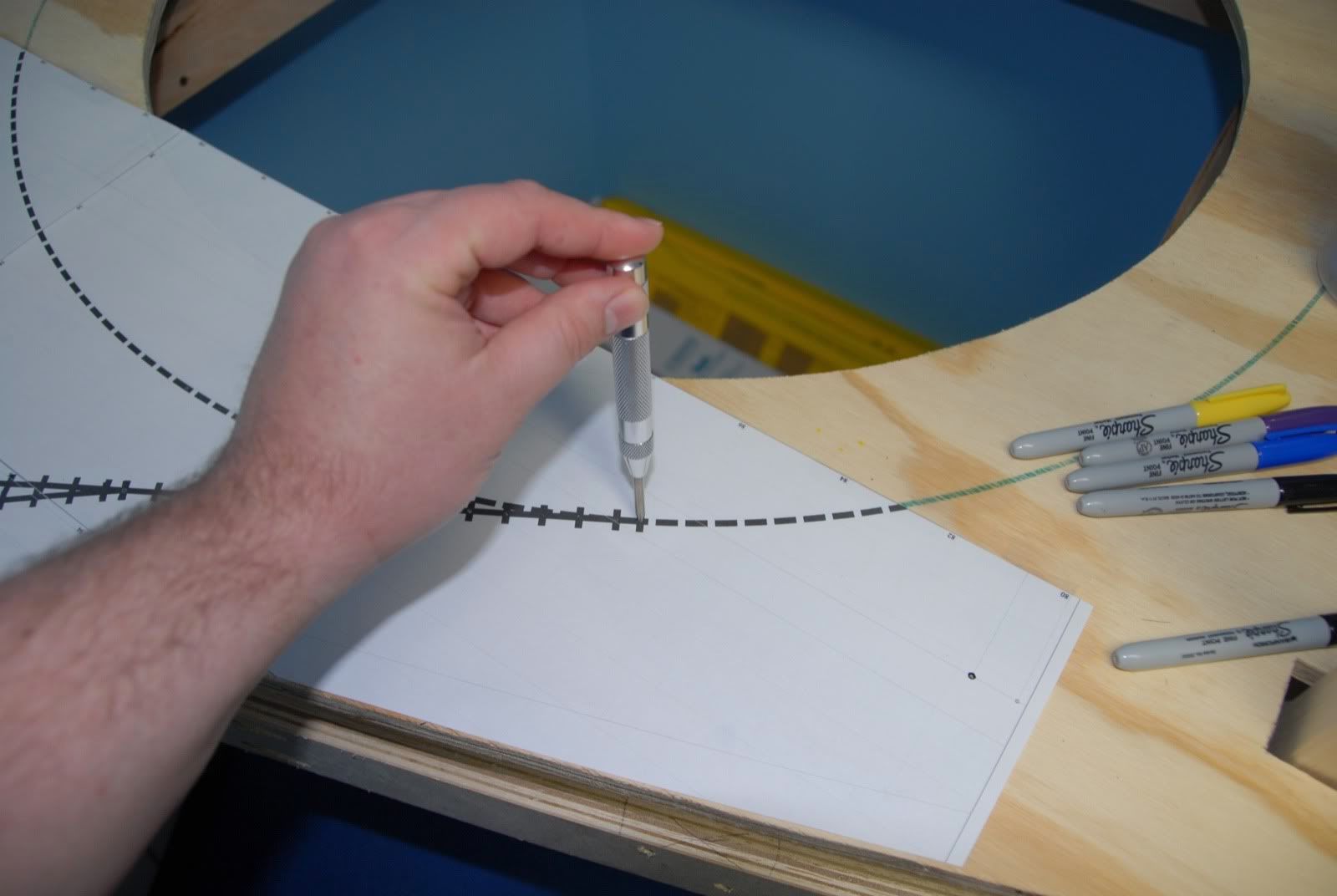
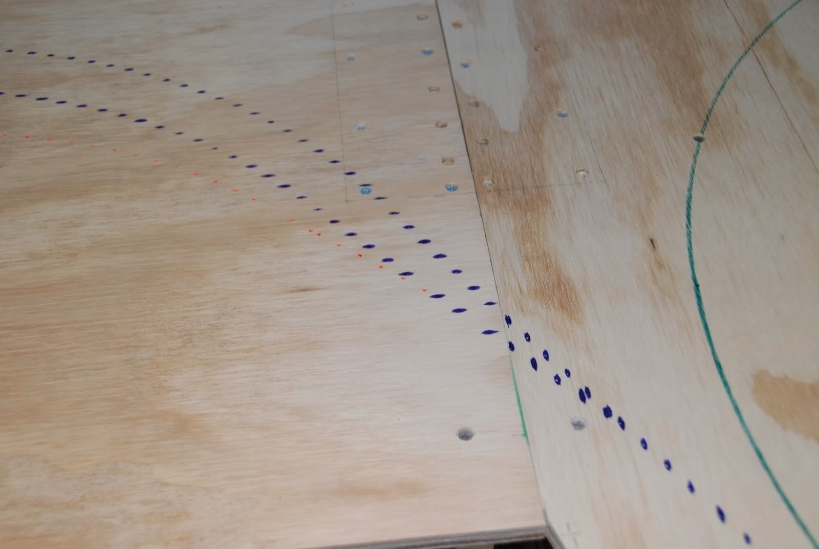
In order to make the mounting go quicker and more precise I made a template out of sheet aluminum for marking where to drill the mounting hole.  It has 2 guidelines, one for the track centerline, one for the turnout throwbar centerline as well as the drill guide holes.


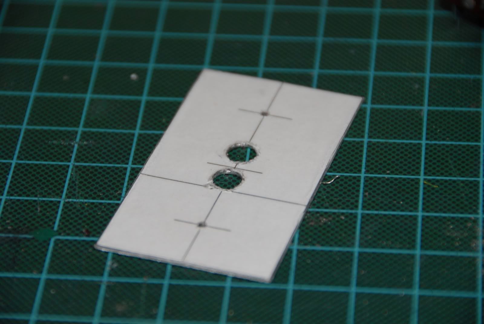
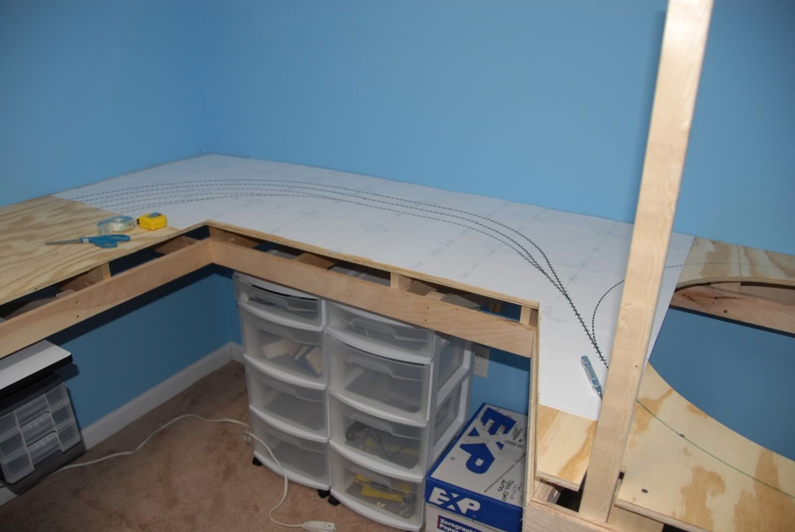
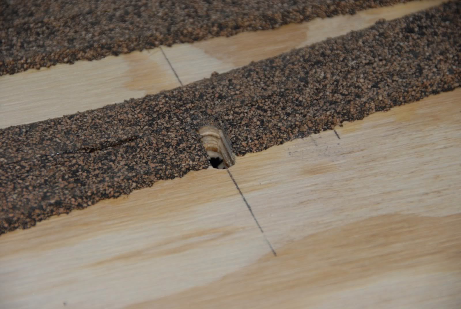
Line those up and mark the two circles with a thin Sharpie.  This will then give you the location to drill 2 1/4" holes.  Once the holes are drilled use a jig saw to connect the holes.  The results will look like this:


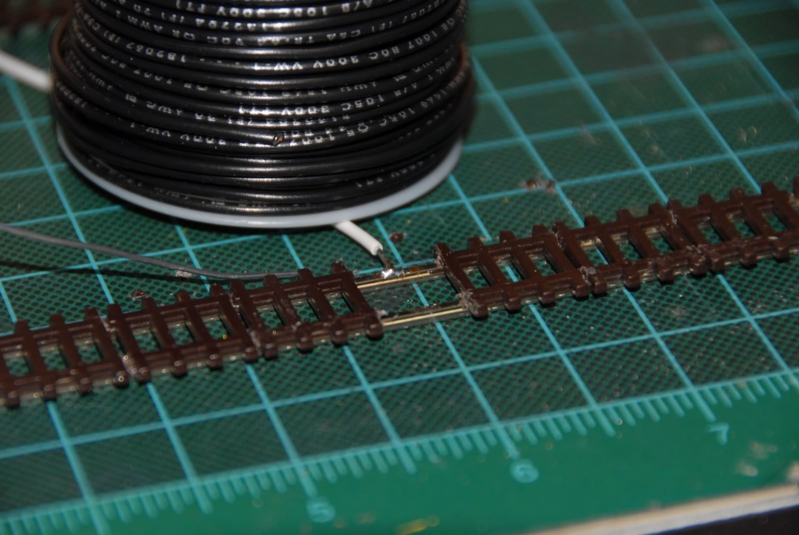
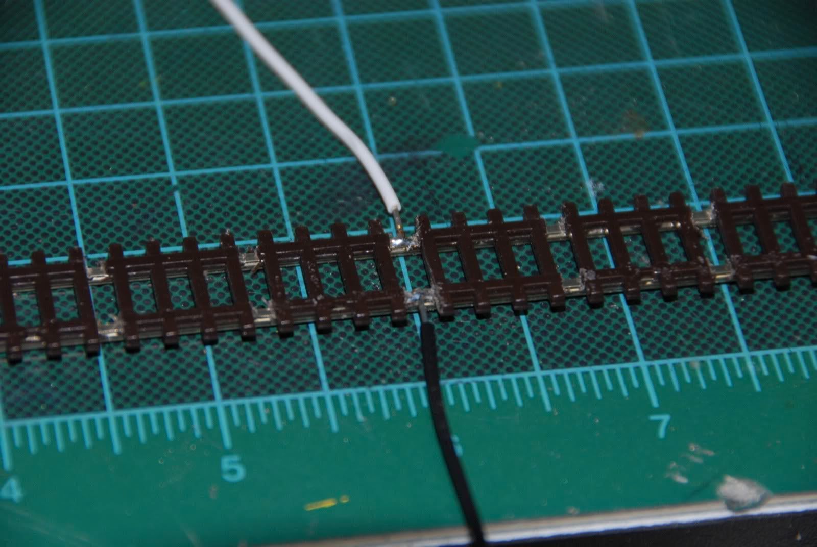
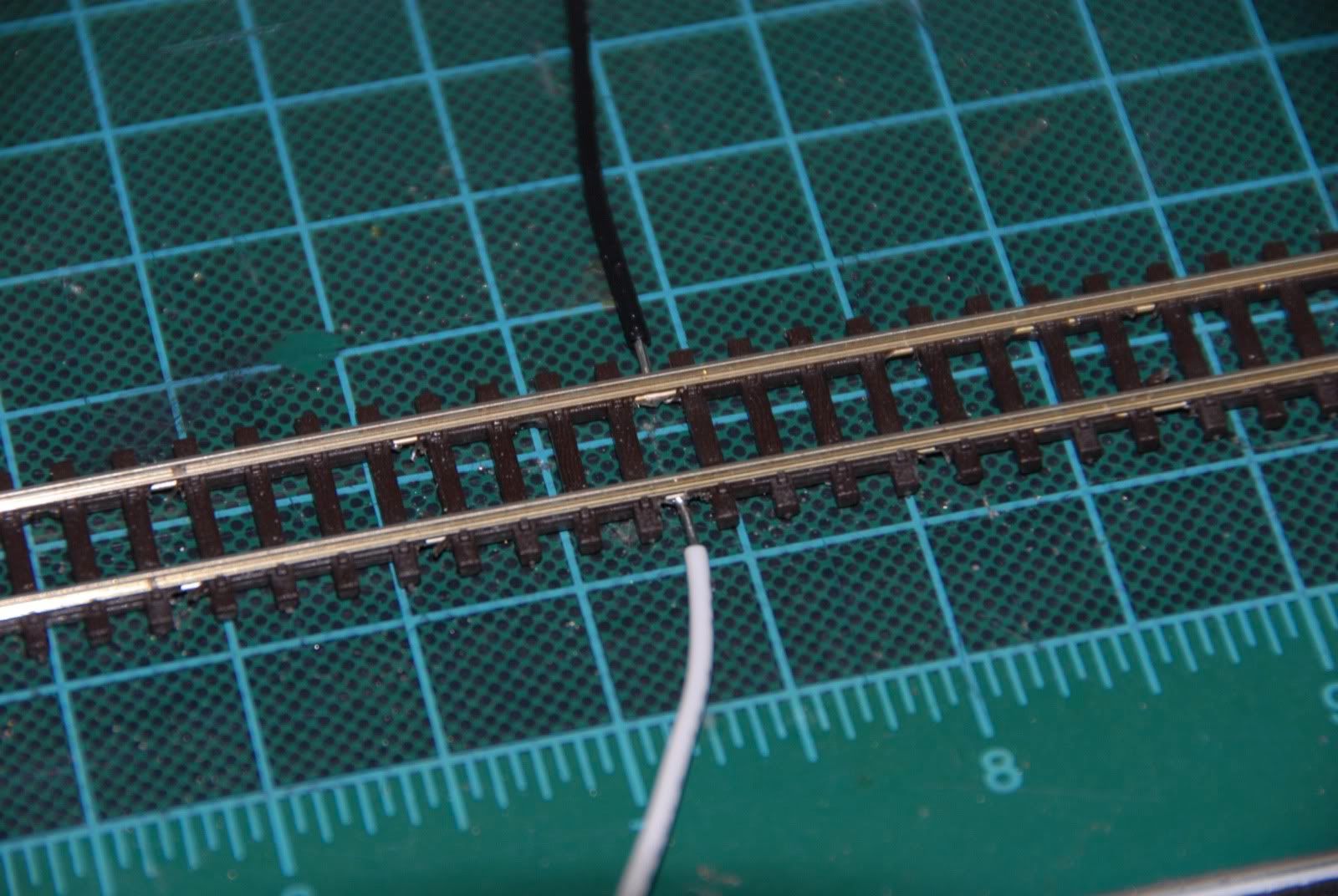
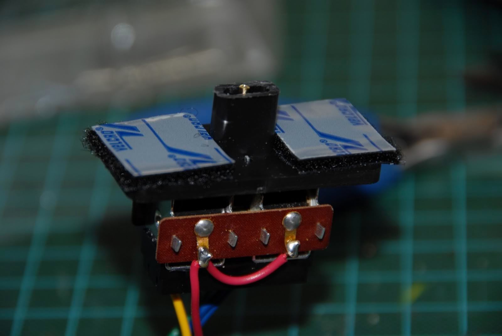
Back to the PL-10/PL-13, solder on some wires.  


Mount the Invis-A-Mount to the PL-10 and bend the tabs of the PL-10 to hold it to the mount.  Finally, I used some industrial strength velcro to hold the whole assembly in place.  The mount comes with screws, however I'm using the velcro for installation/deinstallation ease as well as adjustability.


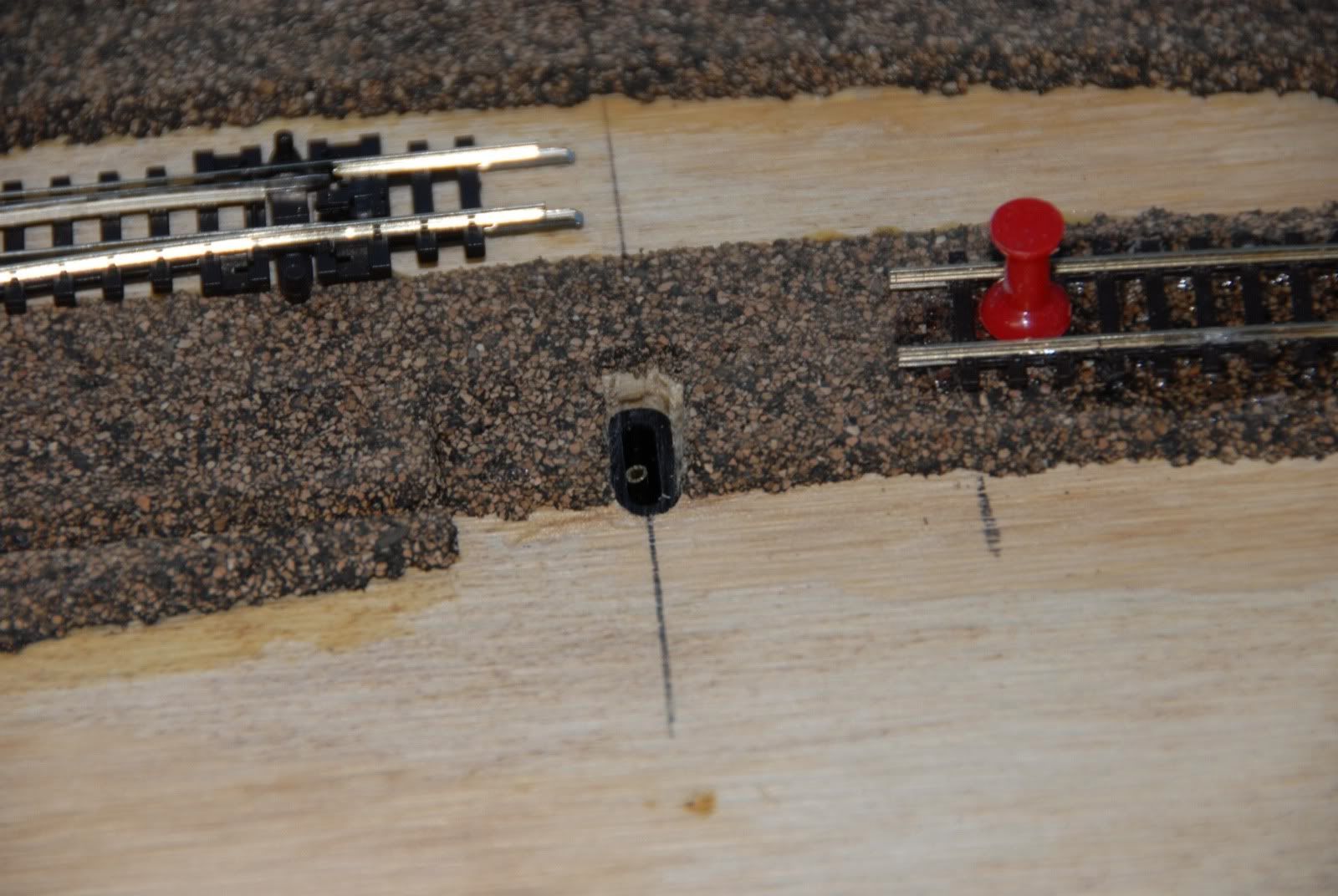
The mount needs to be trimmed to match the plywood thickness as does the extension tube which goes between the PL-10 and the turnout.  Attach the whole assembly to the underside of the layout.  You can see it peaking out thru the hole.


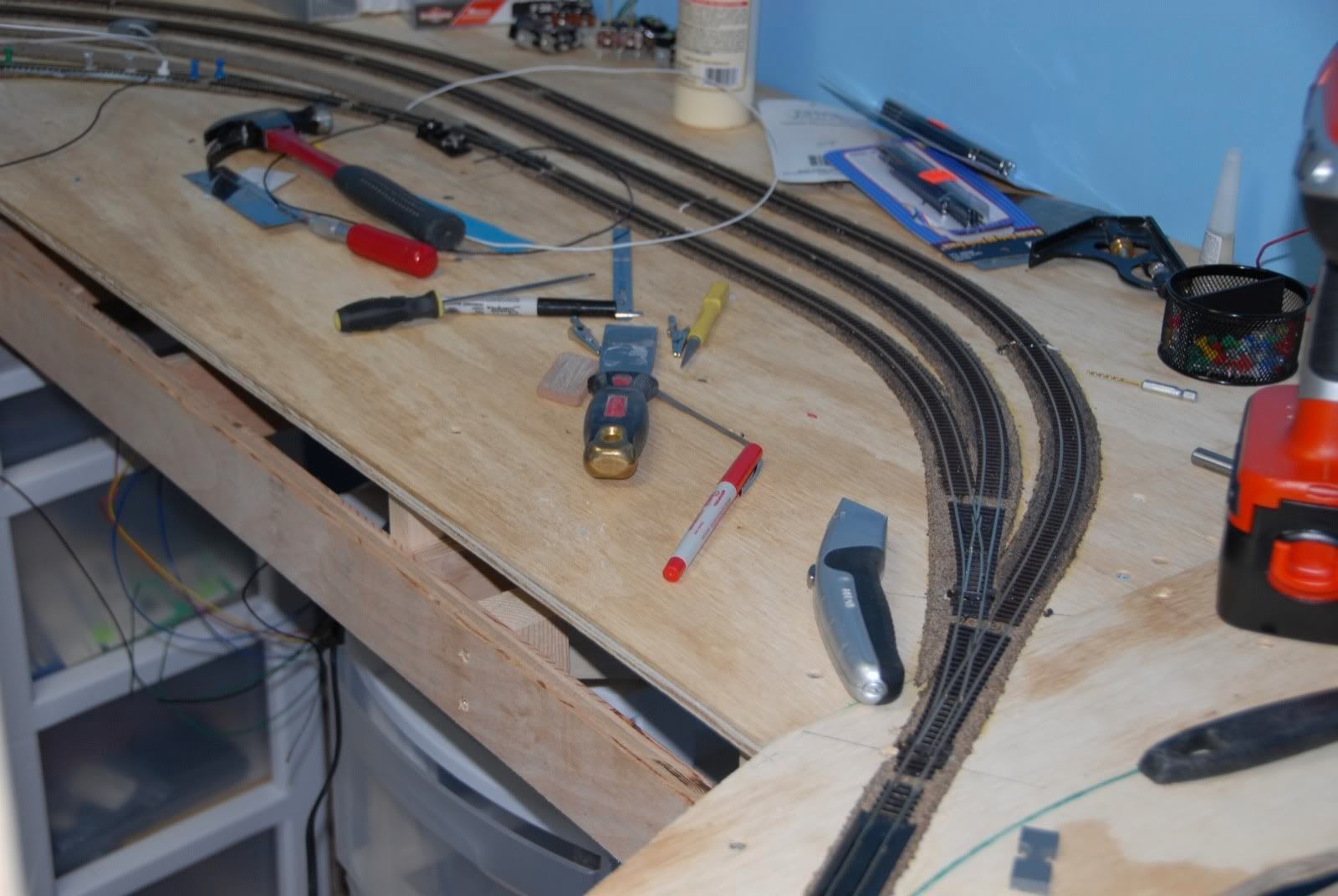
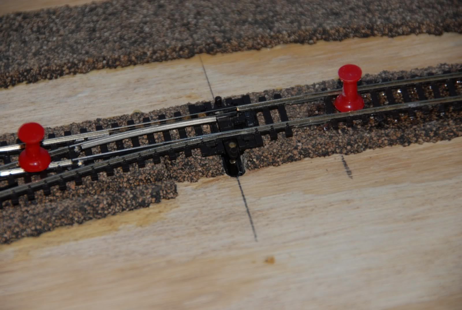
Finally put the turnout in place, connecting it to the undertable assembly with the included nail going to the extension tube.  Test it and it's ready!


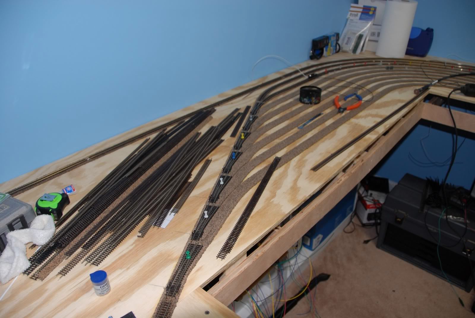
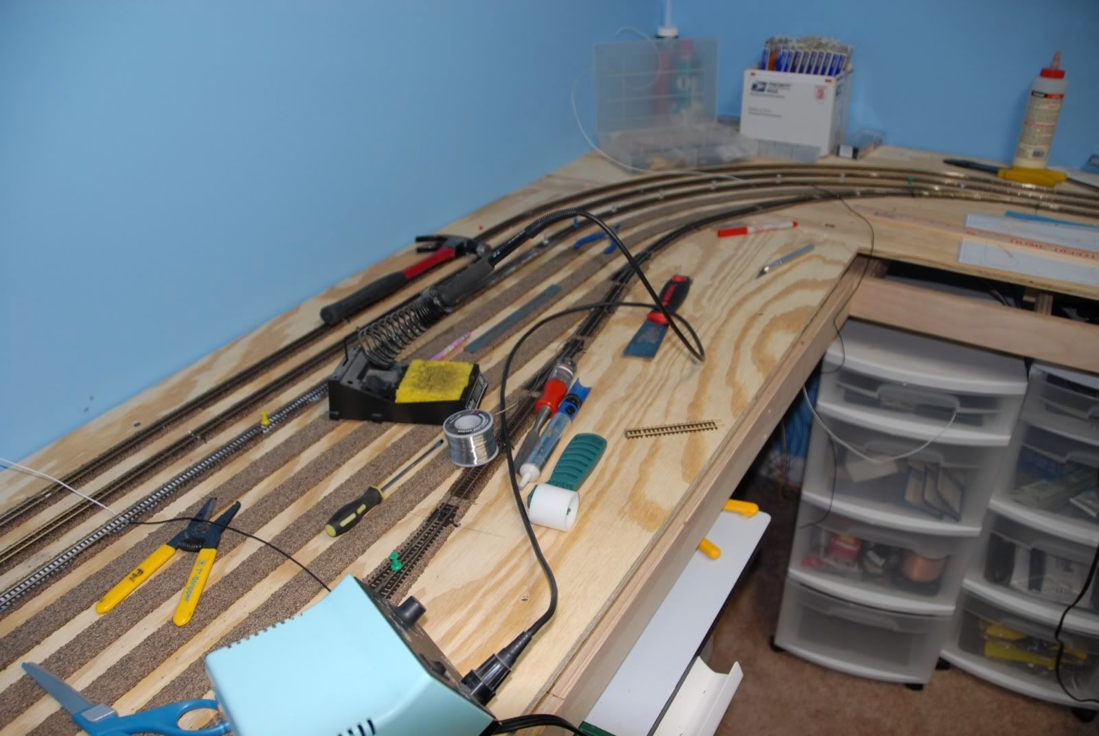
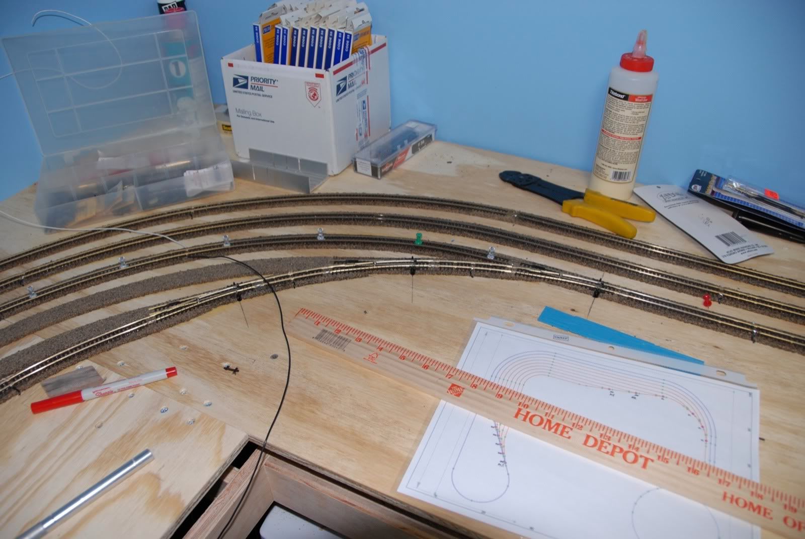
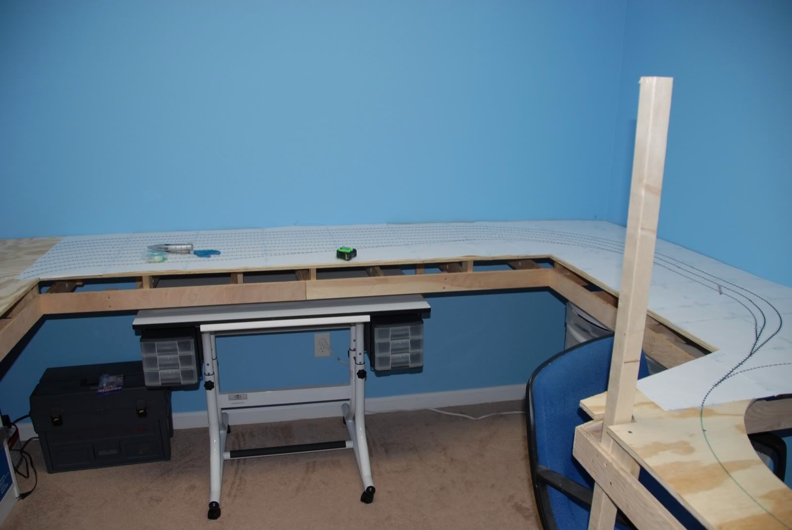
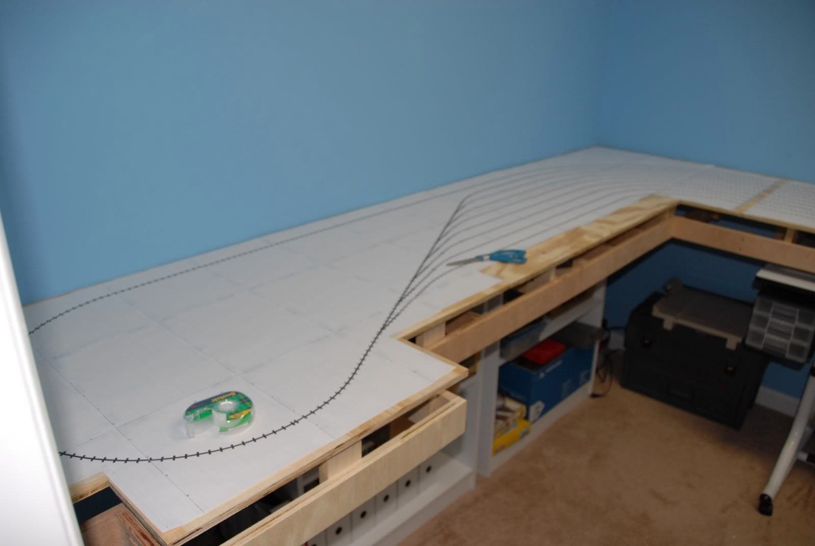
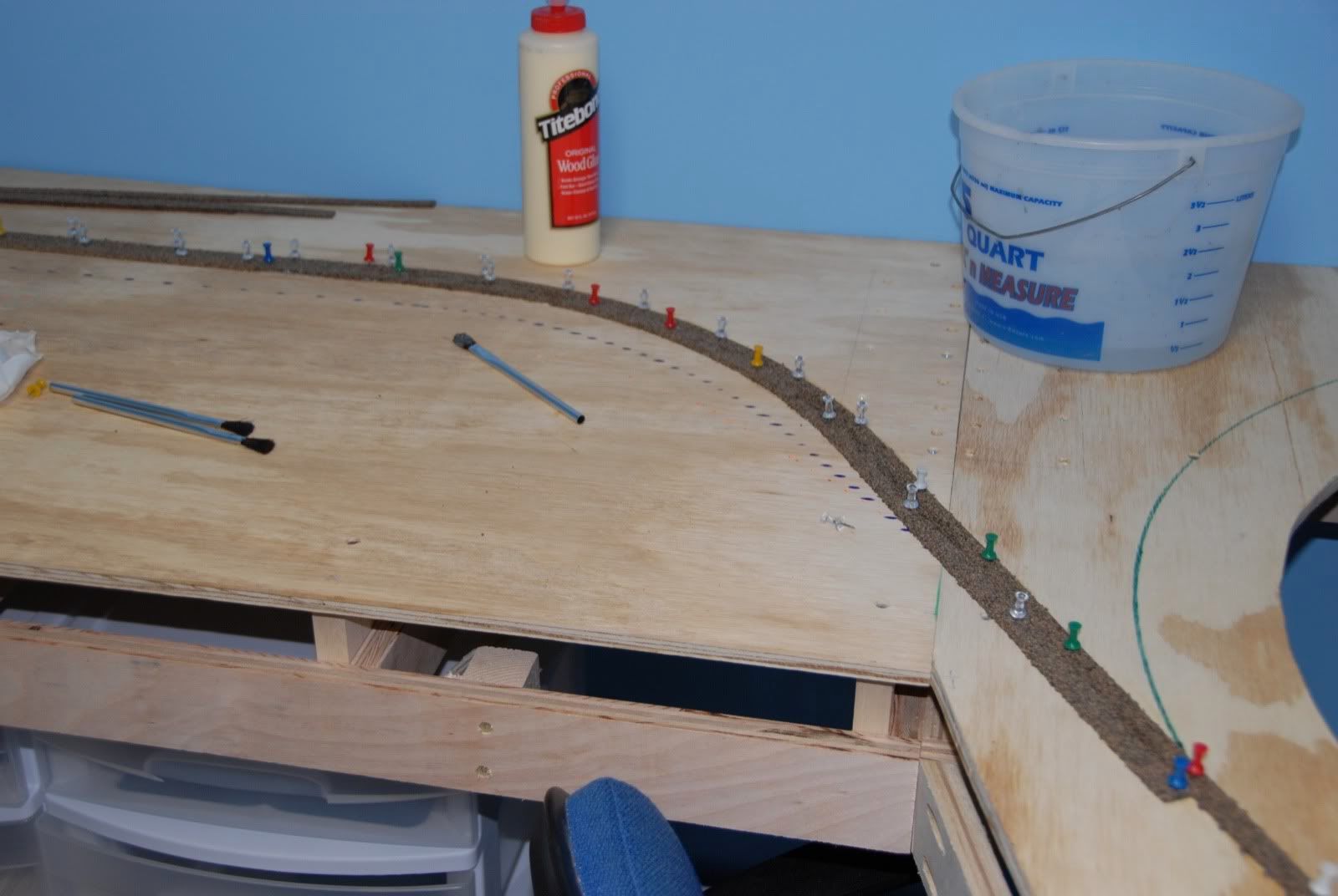
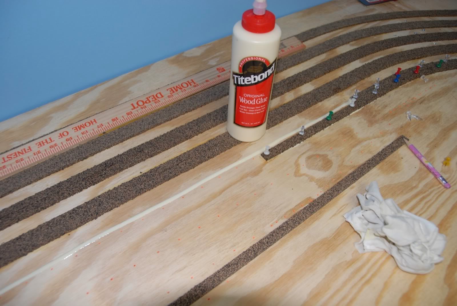
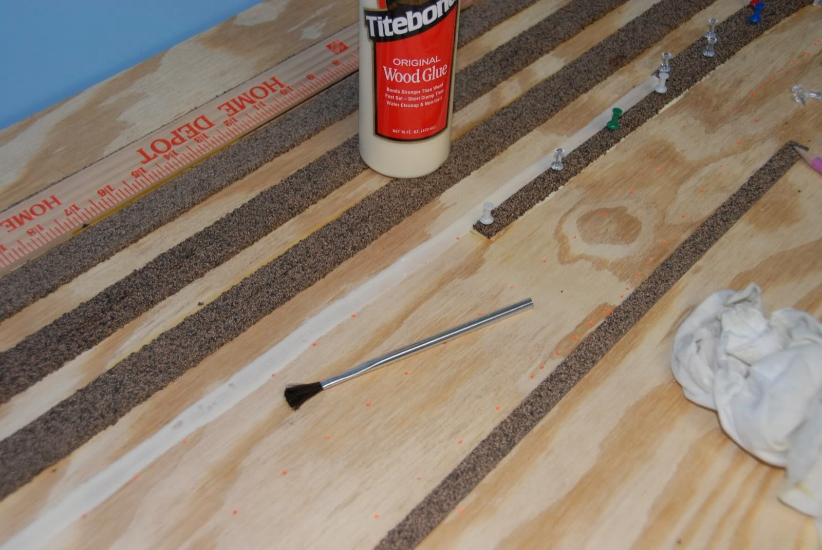
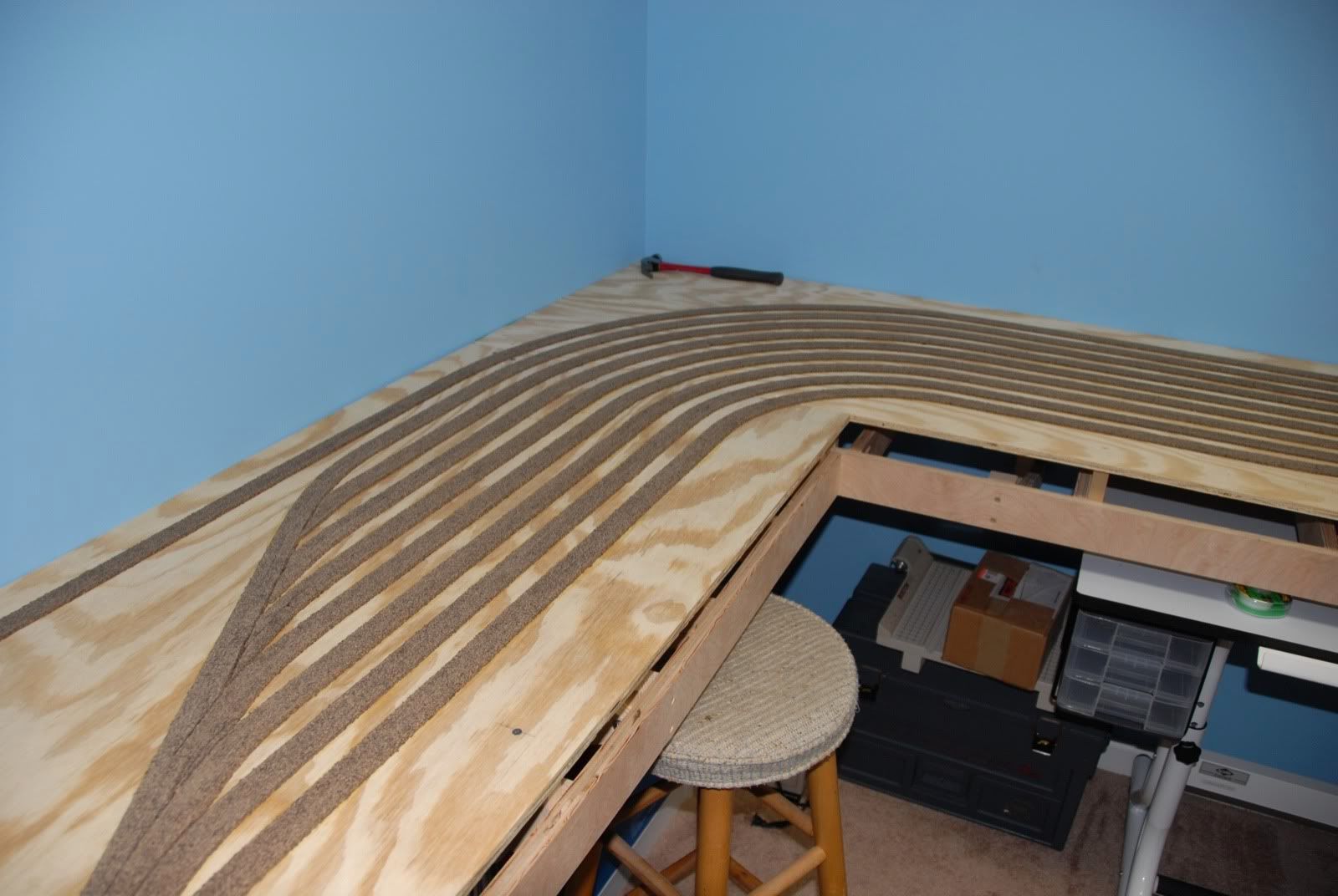
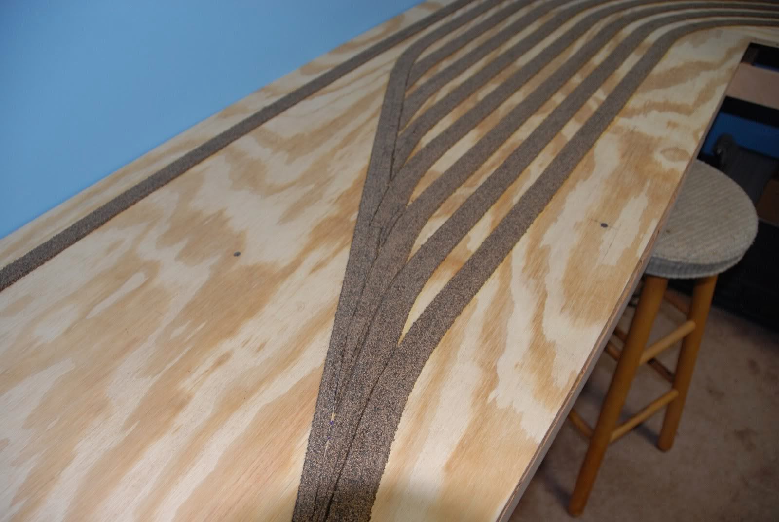
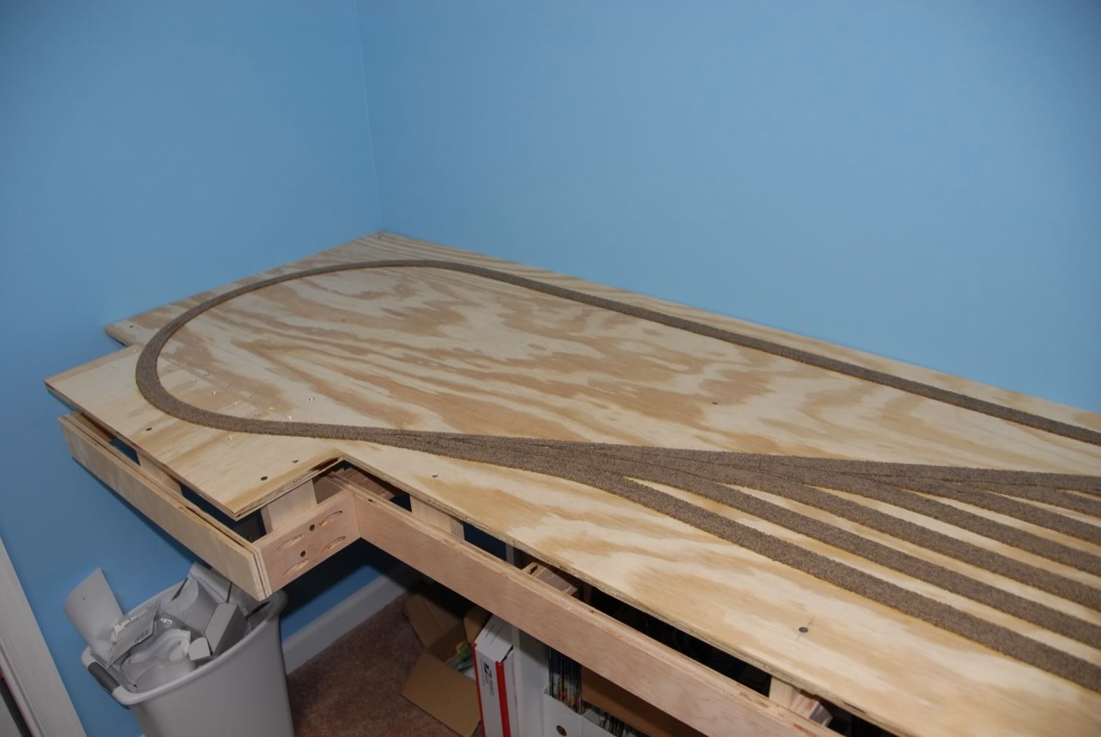
As I said at the beginning of this post the turnouts are in place, as is the flex for the mainline.  The flex for the staging tracks is about a third of the way there.  Once the track is in place I will go back and finalize all the blocks using a Dremel to cut the rails for the blocks as well as complete all the feeders.   Then the undertable wiring begins.....


Sunday, January 24, 2010

Layout Progress Report #5 as of 01/24/2010

Another busy week on the Cahaba Southern, unfortunately there isn't that much to see in terms of changes.  Started off the week putting some Digitrax DCC decoders into some locomotives so that the fleet will at least be partially ready once the track is laid.  Speaking of track, there are 2 things I'm doing on this layout for the first time:  Using undertable turnout switch machines for the Peco turnouts and using adhesive caulk to secure the flextrack down to the cork roadbed.

I've gone with using Peco turnout switch machines mounted undertable, and spent an evening figuring out the easiest way to mount them, as I have 30+ to install, and I want to install them as I'm going along.  I'll describe how I mount them in a future post.  As for the use of caulk for laying the flextrack, it is working well, however it is slower than nailing down the track.   There have been many articles in the literature on how to do this, so I won't bore y'all with the details.

Speaking of flextrack, one of the things one has to do is provide power to it.  Soldering feeders is the way to go, however I wanted to make the feeders invisible once the track is down and ballasted.  First, take the track and turn it over.  Look for the gaps on the flexible rail, those mark where we want to do our work.  Remove the plastic backing on the opposite rail from the gap using a razor saw.  Be sure to just cut through the plastic and not the rail, as shown in the following picture:


Cut thru 5 adjacent gaps and use a pair of pliers to remove the remaining plastic, being careful to damage the ties.  It should then look like this:


Slide the 4 sections apart, leaving a large gap in the middle as shown:


Take a small file and roughen up the bottom of the rails.  This will give the solder a better surface to adhere to.


Lay the 20 gauge wire as shown and solder using some 60/40 rosin core solder.   Here is the wire laying down on the rail, held in place.


One thing I highly recommend is a good soldering station.  You want higher heat than you can get from your standard $20 25-watt soldering iron, as the higher heat let's you get the solder melted quickly, as taking too long will melt the plastic of the ties.  I use a Weller station with adjustable temp, which I have set to 750F.  Here is the wire should look after soldering.


Here are both wires soldered to the track:


File the solder smooth on either side of the wires, and then slide the ties back into place.


Turn it over and you are done.  As you can see the ties are back evenly spaced, and no large solder blob visible on the side of the rail.


Lay the track and cover the wire with ballast, making an invisible power feed.

One final pic of this post, showing some of the progress this week.  Excuse the mess, work in progress!!

Monday, January 18, 2010

Layout Progress Report #4 as of 01/18/2010

Another busy week working on the CSR.  Spent about 3 evenings printing out the 1:1 scale trackplan out of CADRail and putting it together.  Printed out on my laser printer, it took a lot of clear tape and adjustments to attach to the benchwork.  Ran into 2 issues:

1) The room and therefore the benchwork is not 100% square.
2) Even laser printers aren't exact in their printouts.

The first I expected, the second I didn't.  Turns out as the laser printer prints the guide wheels are effected by the grippiness of the paper, causing some minor slipping of the paper as it feeds thru.  Just had to work around it and made the best of it, and the results were as good as I had hoped for.

Started out at the helix, as I already had a reference line, i.e. the helix circle drawn on the wood.  Also visible is some new storage containers that fit perfectly under the layout.


As we work around the room you can also see my new worktable, a drafting hobby table that has rollers allowing me to store it under the layout as well.


Here the unsquareness of the room came out here.  I made the best of it by extending the straights in the staging yard.


Whew!! That was a lot of paper and tape but made it all the way around. Highly recommend using a paper cutter.


Now how do I use this taped down trackplan??  I've seen some other layouts where the paper is glued to the benchwork, and then the cork/vinyl roadbed is glued to the paper.  The more I thought about it, the more I didn't like it as I was worried about the things coming unglued.  I decided to do something different:  Punch small holes in the paper into the wood and then color the holes.  The next picture show the automatic centering punch I used for this.  Put holes in about every inch in curves and 2 inches on straights.


Once I had the holes punched (2 hours later) I followed up with some colored Sharpies to match the colors of the trackplan.  Results are visible in the next 2 pics, purple is the loops,  orange is staging.


The colored dots became the centerline for the cork subroadbed, glued down with yellow wood glue and tacked in place until the glue dries in about 30 minutes.


In the next few pics are some more details of how I glued down the cork.  First lay down a bead of glue:


Then using a small disposal brush spread out the glue about cork width to help with even adhesion.  Lay the cork on this, making sure you press down firmly the entire length, tak it down, and remove any glue seepage with a damp cloth.


Here is some of the trickier cork laying around the yard entrance.  Make sure to have plenty of tacks on hand!  This section took a couple of hours by itself!


Once dry I followed up with some drywall sanding mesh attached to a sanding float and smoothed out the top of the cork,  Made short work of it and resulted in a perfectly smooth surface.


The completed cork roadbed on the lower level:


The cork is down in a weekend, not too bad for a one man crew!

Next comes some trackwork and beginning of the wiring for this level. Things will start slowing down here, so until then.......

Sunday, January 10, 2010

Layout Progress Report #3 as of 01/10/2010

Well, it took a strong push last Thursday and Friday night, as well as most all day Saturday & Sunday to complete the basic benchwork for the lower level.  This has been a tiring couple of weeks to get this far but well worth it.  The one thing I miss about the old house in which my first Cahaba Southern was located is that the room was in the basement without carpet, so I was able to work on the woodwork in the room itself a bit at a time.  Here in this house the room is carpeted and off the downstairs den, so no major woodwork is possible in there.  All the heavy duty sawing and cutting has to be done in the garage, and in particular in my wife's parking spot.  Therefore, getting the woodwork knocked out without leaving the table-saw and miter-saw out (as well as my wife's car in the cold) for an extended period of time has been a priority.

Risers were cut from 1x3 poplar Thursday night and installed Friday night.


Saturday morning it was off to the Big Orange Retail Giant (BORG), i.e. Home Depot, to purchase some 1/2" BC 4-ply plywood as well as some some more screws.  I had the BORG staff cut the plywood into more manageable 2 foot wide sheets as well as cut them to appropriate length (still had to trim them by 1/4" once I got home).  Installing the 3 straight sections going clockwise from the left of the door took the rest of the day.


Saturday evening it was time to look at the helix area again to see if/how my plans would actually work.  I had to make some adjustments, the biggest being that there was not enough room for the helix supports with an 18" radius, so I had to decrease it to 17".   This would make my grade 2.34% with a 2.5" top-of-rail to top-of-rail rise, still below my goal of 2.5% maximum.  I also decided it was best to go back to the BORG and get another piece of plywood and build the helix base out of one piece of plywood instead of splicing some smaller pieces together as I had originally planned.  This will give a sturdier base of the helix, and will simplify the building of the helix support structure.  The 17" radius circle is shown on the helix base, and the hole was cut to a 14" radius.


So now the lower level base benchwork is complete,  the saws have been put up, sawdust has been swept up, and my wife's car is back in it's spot. Next it's time to start on laying out the cork roadbed and the track, as well as starting some of the wiring.  Once the lower level has it's track and wiring completed it will be time to build the helix, followed by the construction of the upper level benchwork.

Friday, January 8, 2010

Layout Progress Report #2 as of 01/08/2010

A couple of productive evenings this week, got the rest of the framework up for the lower level. I also built and put in a couple of small bookcases for under layout storage. Here are a few pics of the progress:


Helix corner to the right of the door:


Another view of the helix, the lone leg of the layout is visible, shared with the upper level:


Left side framework table, bookcases shown underneath:


Another view of the left side framework of the lower level:


Next are some risers and then comes the subroadbed plywood!