Showing posts with label Benchwork. Show all posts

Saturday, November 27, 2010

Layout Progress Report #21 as of 11/27/2010

Well, the big day finally arrived on Wednesday, November 24th:  Both mainlines' track was completed and the first trains ran on them on the main level, 327 days after the first piece of benchwork went up.......Hooray!!!!  It's been a long haul so far, and the journey of this layout has a long way to go!

Here is a video showing the mainlines in operations as of this morning:


Here are some pics to look at things in more detail.  First the loops around the coal mine area:
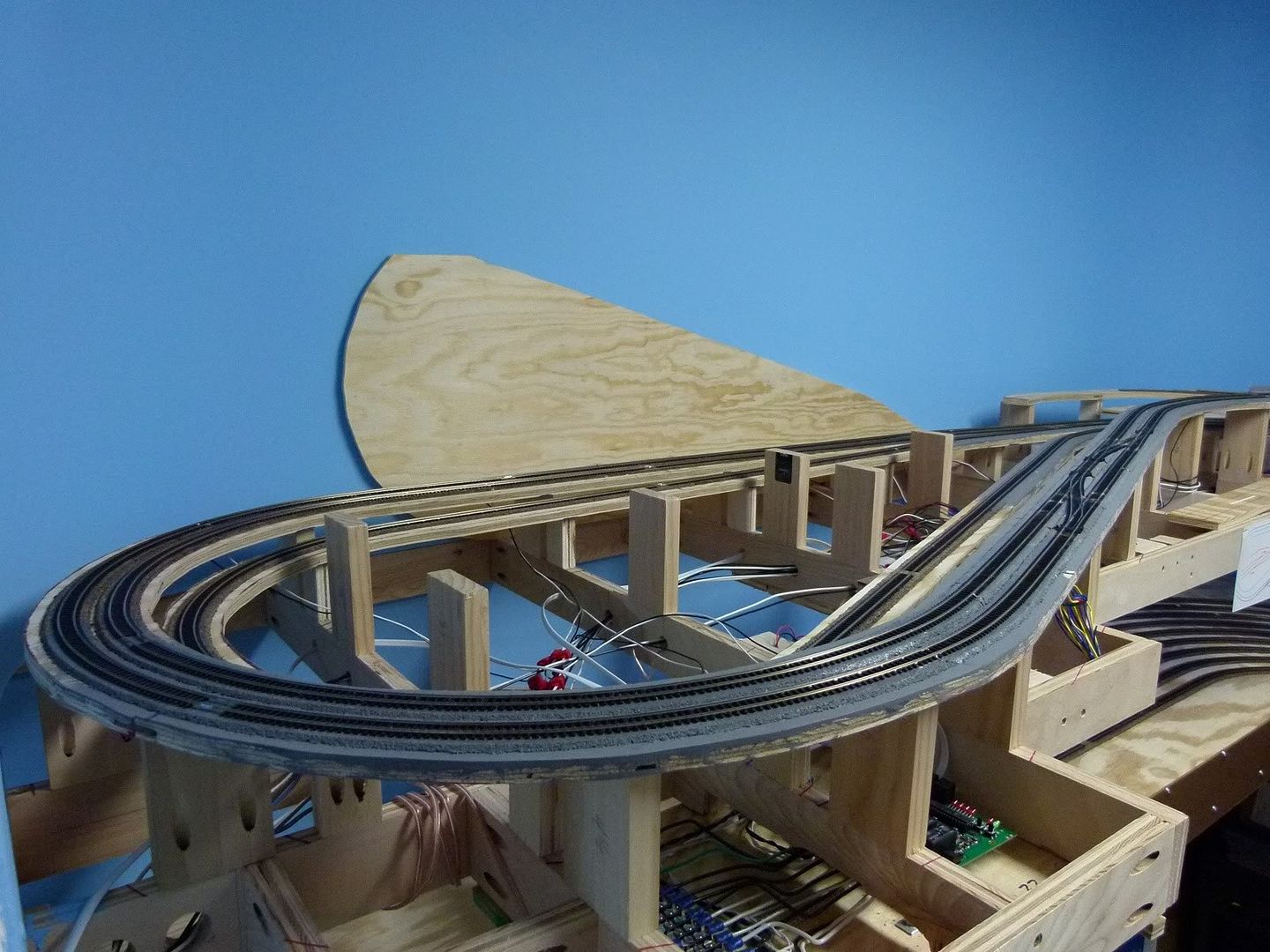


Next the area heading into the town (one of these days I'm going to have to start naming these places)....
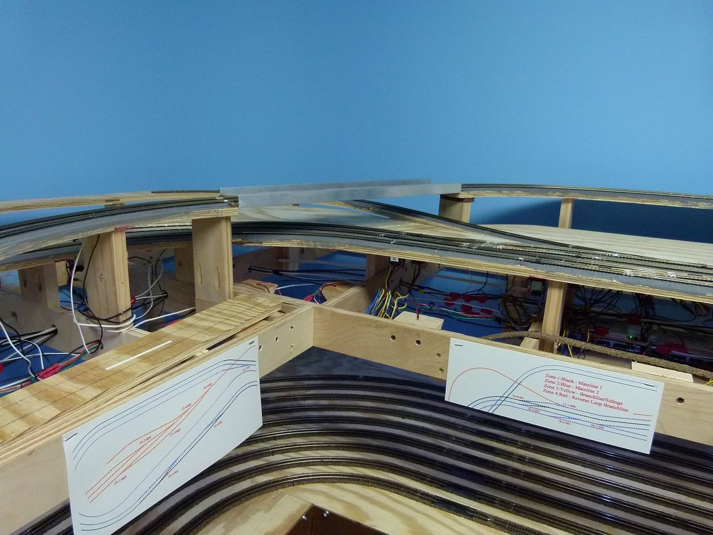


A further look around the town area toward where the depot will be:
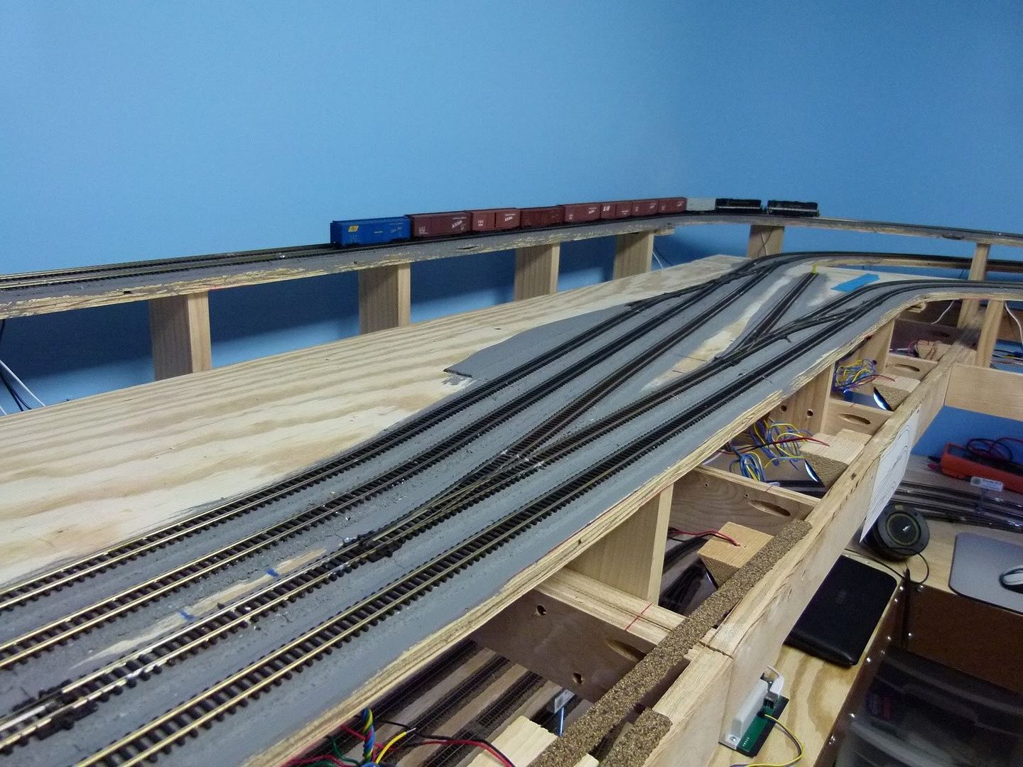


Continuing further east along the layout:


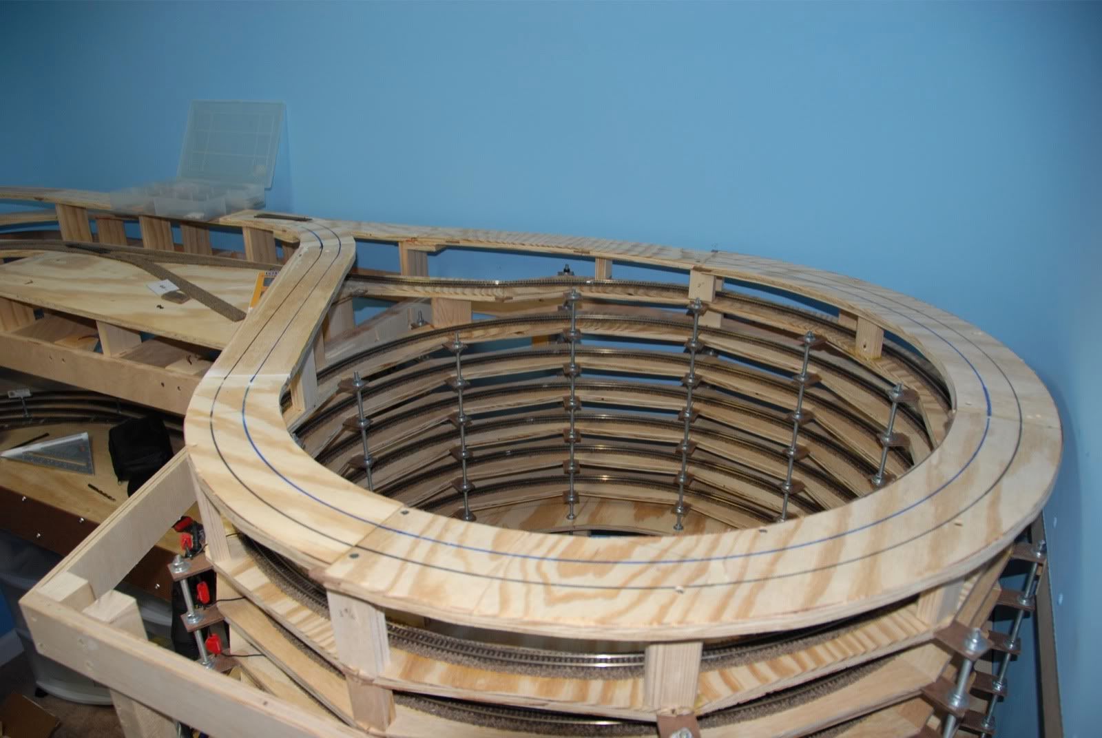
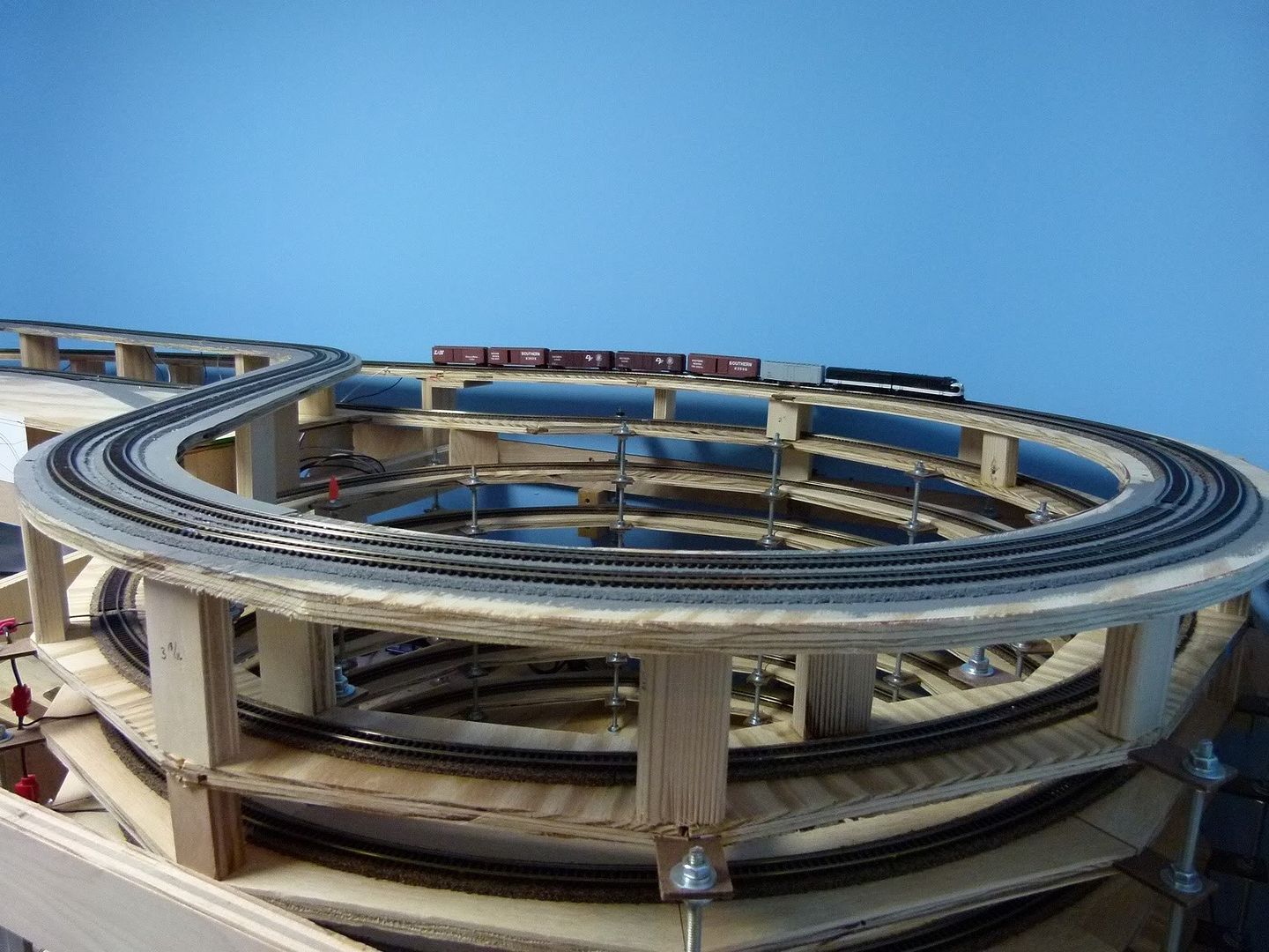
Finally the loop above the helix:


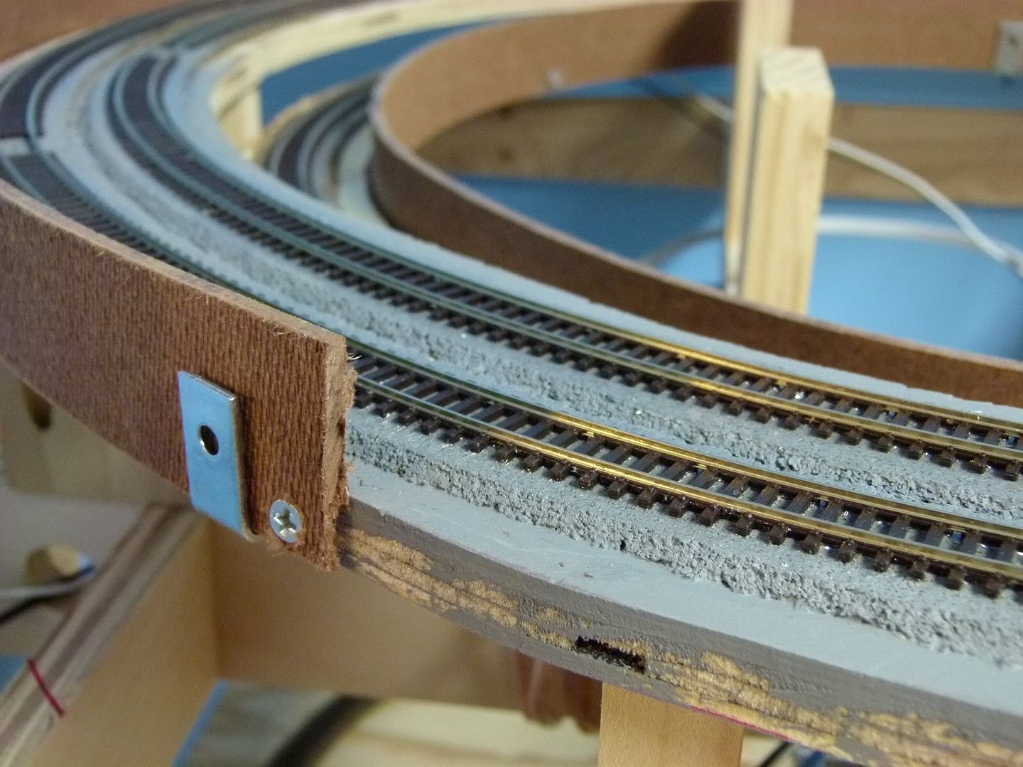
After the video and above pictures were shot, I began to work on some train protectors along the hidden part of the track.  These protectors will help stop the engines and/or cars during a derailment from falling off of the roadbed on the upper level onto the lower level or, even worse, onto the floor.  With the cost of rolling stock these days it only makes sense to do this to help prevent destroying the rolling stock.  I'm only installing these on what will be the hidden track, as the visible track will have scenery around it to catch any derailments.

I'm building these with 1.5" wide strips of 1/8th inch masonite hardboard and some 1 inch corner brackets screwed to the bottom of the wooden subroadbed.  Here is a closeup that shows how it is mounted:


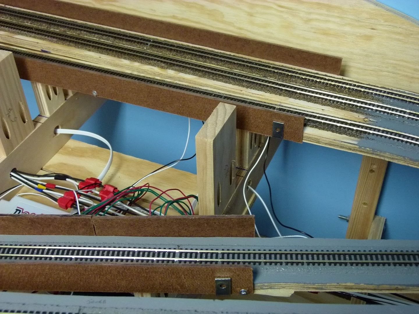
Here is another area showing some of the protector boards.  As you can see, the corner braces hold it in place, with a few screws here and there to secure it.  Doesn't have to be pretty, just effective:


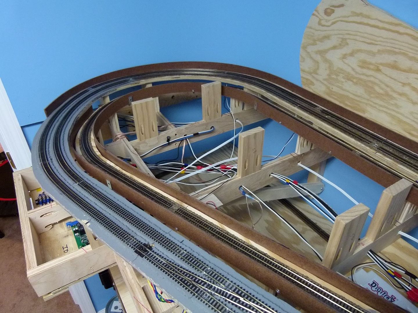
Here is the coal mine part of the layout with all of the protector installed on that side:


Next couple of weeks things will slow down some, with the holidays approaching.  I'll work on a few odds & ends during that time, mostly some DCC stuff like installing decoders and working on routes.  However, I already have plans made for over the Christmas holidays to pick up some styrofoam sheets to start the scenery contours!!

One final video before we go.  I shot this for our friends at N Scale website, a great resource for the N Scale Model Railroader.  See y'all soon!!!


Sunday, August 22, 2010

Layout Progress Report #17 as of 08/22/2010

Just a quick progress report on the Cahaba Southern:  It's been a busy three weeks since the last update, and the good news is that the major benchwork on the upper main level has been completed!!  Yes, it is time to start trackwork and electrical on the main level.

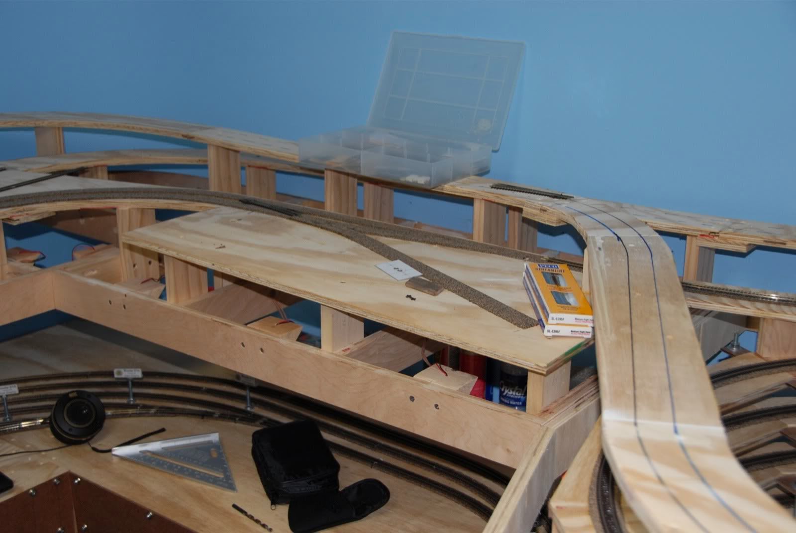
In the following picture the double mainline can be seen looping above the helix.  Getting the elevations right for this loop turned out to be fairly since I had detailed elevation measurements from the trackplan.  All the elevations on the trackplan were with respect to the top of the benchwork.   I measured up the  amount of the elevations above the benchwork on the wall, and made a mark.  Next I broke out my self-leveling laser line level to match that mark.  I then held a ruler above the actual location and was able to determine the exact height of the riser by where the laser line was hitting the ruler.  After the risers were in place the wood subroadbed was cut and then put in place.  The results can be seen below:


Here is another pic a little further down the benchwork.  As you can see I have started the cork roadbed and getting ready for the track laying.  I actually had to lay the track coming from the helix to the branchline before the benchwork for the double mainline in the previous picture was put into place.


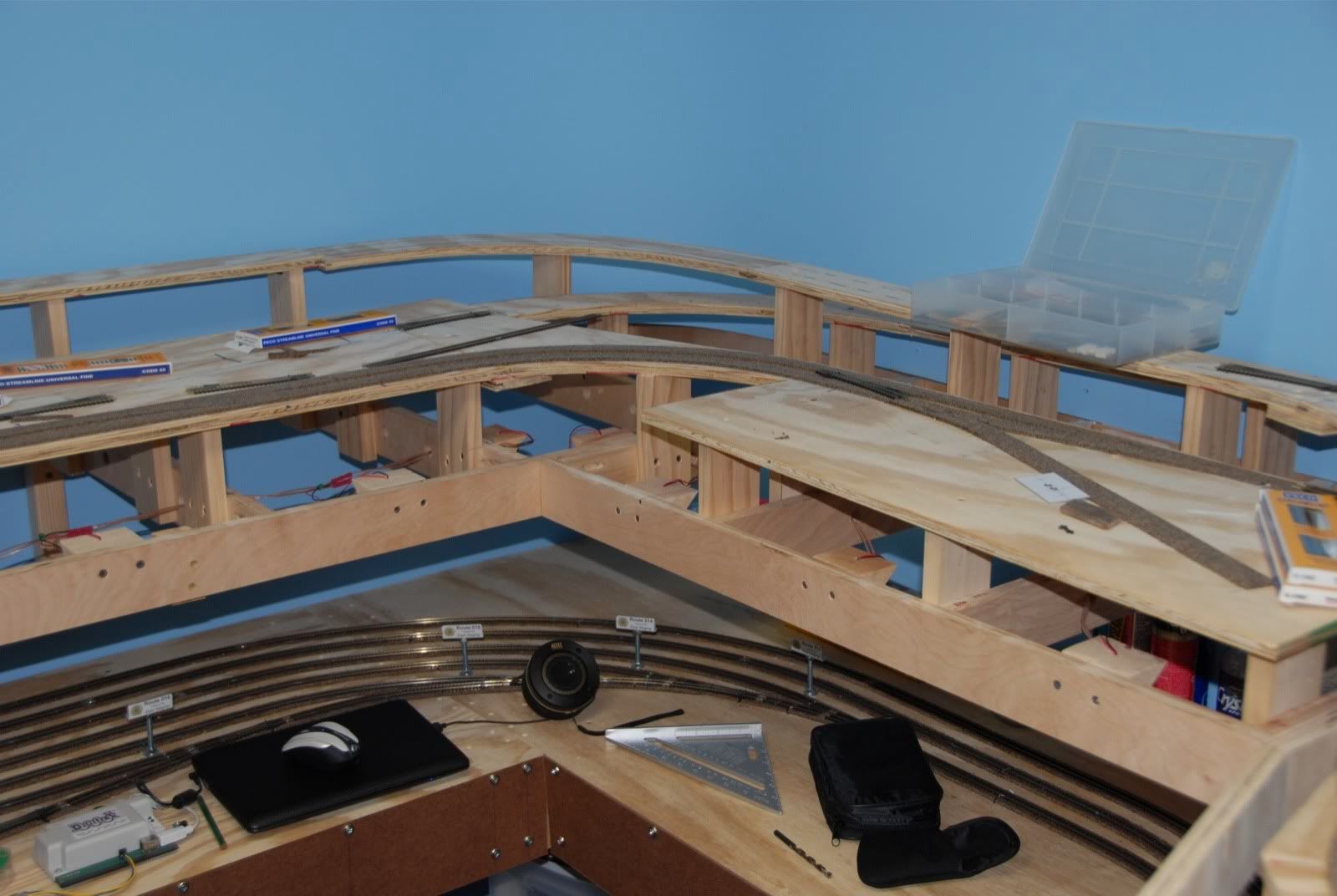
The following pic shows the some more of the complete main level benchwork.  Also, if you look closely I have mounted the front fascia for the lower staging level to give things a more finished look.  It will be painted green later on.


This picture gives you a closer look at the different mainline elevations above the helix.  Couldn't imagine doing this without a detailed trackplan with exact measurements, be it a trackplan out of a magazine or book, or one drawn up on a CAD package.


This final pic shows the rest of the cork roadbed in place on the branchline return loop.  It will more than likely be up and running before the mainlines, as those will require some bridge construction that I haven't started yet.


Until next time.........

Sunday, August 1, 2010

Layout Progress Report #16 as of 08/01/2010

As usual with most model railroads things slow down in terms of layout progress in the summer months, and the Cahaba Southern is no exception.  However, progress is still being made.  With my last post the plywood subroadbed had been cut, and since then I have been putting in risers and connecting the new subroadbed to the helix.  At this point the main lower subroadbeds are in place, and next are the remaining higher subroadbed for the double track mainline.

Here you can see the first of the subroadbed set to the appropriate height with risers, and then connected to the helix.


More subroadbed on risers in the town area of the layout.  The higher subroadbed visible in the back is not attached yet to the risers, it is just laying on them.


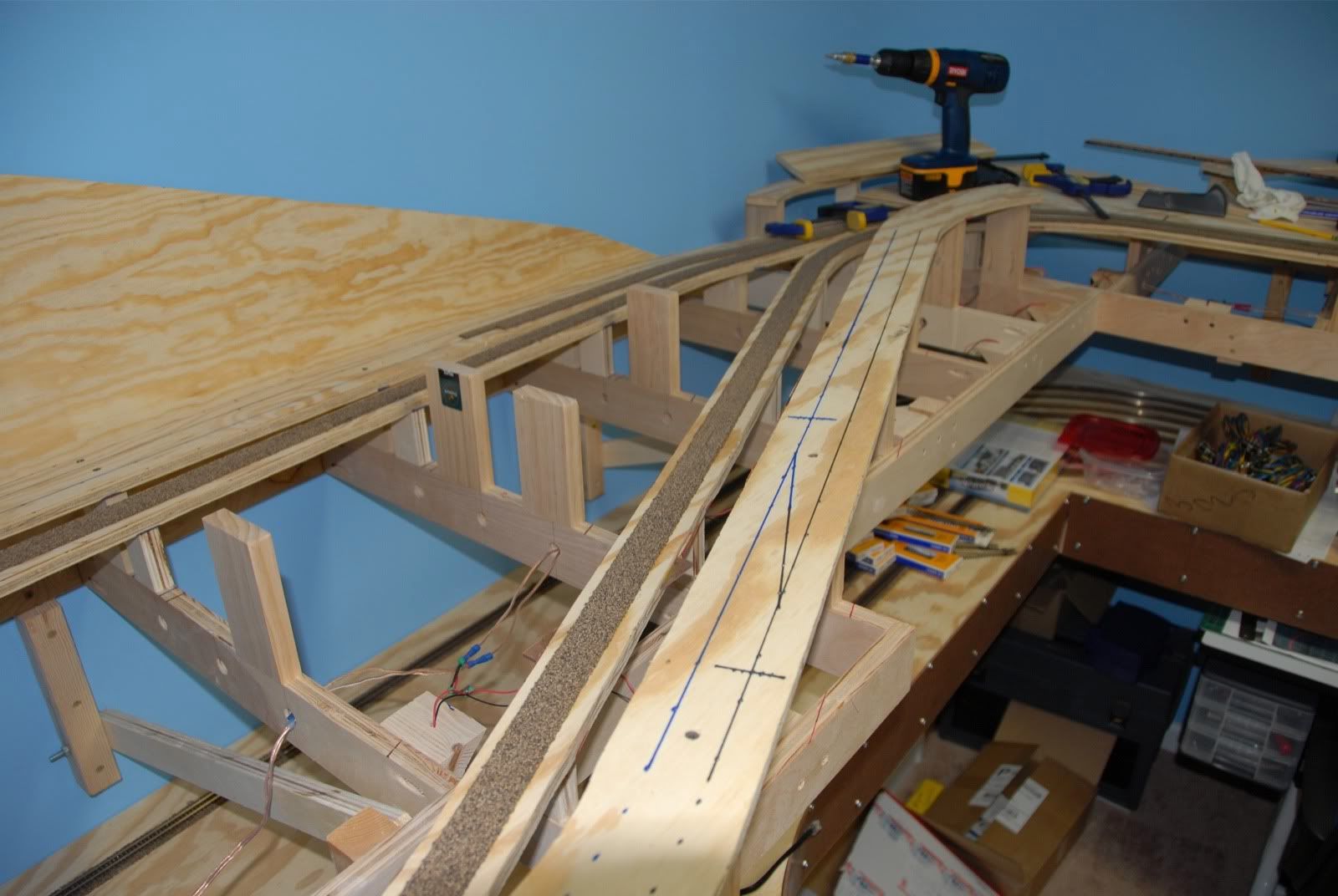
Here you see the subroadbed leaving the town area heading up towards the coal mine.  This picture shows the true beauty of using cookiecutter benchwork..  As the subroadbed starts to rise towards the coal mine the transiition is perfectly smooth, which will give a natural flow to the trains going up/down this transistion.  The bend of the plywood makes it perfect.


Up until this point I have been installing the risers by clamping them to the joists, leveling them to the correct height, and then screwing them to the sides of the joists.  This is tedious and takes some time. As I was getting ready to install the risers around the coal mine area I discovered that I was going to have to install some right over the wiring holes in the benchwork, effectively blocking them.  No problem, I'll just cut those to the correct height and use pocket screws to mount those to the top of the risers........

AAARRRGGGGHHH!!!  DOINK!!!  Well DUH!!  Why hadn't I thought of that before, it would have saved a lot of tedious work mounting those risers.  I have the exact rise needed from CADRail, the grid benchwork underneath is level, and I have an accurate miter saw and the pocket hole jig.... this would have saved me about a days worth of work if I had done all of the other risers that way!  Armed with my revelation I was able to knock out the remaining risers needed around the coal mine in about an hour instead of the 6-8 it would have take the other way.


I was then able to attach the subroadbed for that area.


I'm not attaching the subroadbed for the mine at this point, I'll do that afer I lay the track around the back of the layout behind the mine area.


That's all for now, next I will continue on the remaining risers for the mainline....

Sunday, June 27, 2010

Layout Progress Report #15 as of 06/27/2010

Wow, hard to believe it's been over 6 weeks since I last posted an update!  Things have been really busy, and the CSR took a backseat to other commitments.  I did get a chance to attend the Southeastern Region NMRA convention.  If you've never attended a regional or national NMRA convention, I highly recommend it.  

Back to the CSR, I've started working on the wooden subroadbed the last couple of weekends.  I'm using cookie cutter roadbed, using similar techniques as in Progress Report #3.  I'm once again using 1/2" plywood for the subroadbed.  I cut the plywood to the size of the benchwork underneath.  Next I print out a 1-to-1 scale layout diagram and attach it to the plywood.  The diagram also had lines on it for the subroadbed.  These will provide the cutting guides for the jigsaw.


I then once again used a center punch and multiple color Sharpies to mark all the lines.  Next I carried the plywood pieces to the garage to cut them in to cookie-cutter pieces with the jigsaw.


After a hour or so of sawing the roadbed was cut and then placed back onto the layout.


Next it will be time to start putting in risers underneath the plywood.  Until then.....

Sunday, April 18, 2010

Layout Progress Report #12 as of 04/18/2010

It's been a busy couple of days on the Cahaba Southern, as the upper main level benchwork was started and completed.  Most of the major wood cutting work had been done several months ago when the lower level was made.  At this point all that needed to be done is for the beams to be cut to length and a few pocket holes to be drilled, as the cross-members were ready to go.  The other part that required some work is the benchwork around the helix, as it required some angled cuts and some fitting around the helix itself.

The first piece of framework is mounted to the walls.  As can be seen in the picture support blocks have been put in place around the walls to help support the framework.  In addition to these blocks which are mounted to the wall studs the framework is attached to the wall studs as well with 3 inch screws.


The second piece of framework is completed and mounted.  It is secured to the wall, the first piece of framework,  and the framework around the helix.


The following picture shows the helix framework in a little more detail.  3 of the outside helix support rods had to be shortened as they were in the way of the framework.  Small wooden spacers were cut to support the helix at those points where the rods were shortened.  I'm sorry that I didn't take any pictures as I was doing this, as I plain forgot too since I was so busy figuring out these adjustments!  Sometimes even the most well-thought out plans require last minute tweaks....


The third piece of framework is in place.


Then the fourth and final piece of framework is installed.


That went quick!!  I guess after the weeks of working on the helix there was some renewed energy to work on the Cahaba Southern again.  Next it will be time to work on the curved backdrop for the main level, as well, as getting some lighting in place for the staging level.  Until then.......

Monday, March 15, 2010

Layout Progress Report #10 as of 03/15/2010

Just a quick update:  The first loop is completed, so I wanted to get a quick few pics of it before I start putting down the cork roadbed and track for the first loop.  I will say this:  when the helix is finished I will use the inside as a tornado shelter!  As flimsy as the rods may look, the wood pieces are solidly in place!


Sunday, March 14, 2010

Layout Progress Report #9 as of 03/14/2010

The fun has begun....the helix, that is.  As previously shown, my layout is 2 levels, the upper scenicked level connected to the lower staging level with a single track helix.  The design specifications for the helix are as follows:

  • Single track 
  • 17 inch radius
  • 2.5" rise per loop
  • 6.5 loop total

Using nominal 1/2" plywood with cork and Peco 55 track this yields a height clearance of almost 1-7/8", with a grade of 2.34%.  This is more than the NMRA recommended clearance of 1.65"

If you do a search on the internet you will find many different techniques for building one, including purchasing some kits to make the helix build simple.  I decided to make the components and build it myself, as it is the most cost effective solution.  Keeping with the cost effective theme meant that cutting the helix loops as semi-circles out of plywood would also not work as it leaves a lot of wasted wood.  I decided to use a technique of making a circle out of 12 straight pieces of wood, with each end of the wood cut at a 15 degree angle.  Here is a CADRail drawing of what it will look like:

With a table saw and miter saw it will be rather straight forward to cut these pieces to size.  I will be able to cut all the wood needed for the helix using one piece of 4x8 plywood.  To join the pieces of wood to make the helix I will cut an 1/8" slot into the edge of the wood and connect them with some 1/8" thick masonite pieces.  The same masonite pieces will be used as supports using threaded rod risers.

I started working on it Saturday morning after a trip to Lowes for the remaining hardware.  First thing was to rip the plywood to 3" wide strips, and then cut them down to the appropriate length with the miter saw.  Here you see the pile of wood strips cut to length:


Here you can better see how the wood pieces will work together:


Now is time to cut slots into the ends of the wood strips.  To  do this I am using my router table and a slot-cutting bit.


Here you can see the business end of the slot-cutting bit with a guide bearing on top.  It will make short work of cutting the slots.


After some serious sawdust the wood strips are slotted.


Then I cut the 1/8" masonite slot pieces with the table saw and miter saw, and drilled some holes for the threaded rods.   Here is the whole pile of parts that will make the helix.


First I made a jig to mark the track centerline on each piece out of a couple pieces of wood.  Doing this before assembly will make things easier.  Once again I will use a punch to mark the line.


Next it is time to grab one circle of pieces and lay it out on the base to see how it will fit.  I also marked where to drill the holes for the threaded rod risers.


The next close-up will give you a better idea of how the helix will be put together.


Once everything is laid out and marked, it was time to remove some of the base where the helix will start.  I calculated that after 3 sections the helix will rise above the base, so I cut a hole with a jigsaw for that.  I also drilled the holes for the threaded rod risers and started putting them into place.


All the threaded rods are in place, secured in place with nuts, washers and loctite threadlocker.


Here you see the first three pieces in place.  The first piece is spliced to the base, with the remaining pieces supported by risers under the base until the first masonite tongue piece is used.


So the helix construction has begun, next time I will continue to chronicle the building of the helix....