The main DCC and power supply area is shown in the following pic. From left to right on the lower shelf the components you can see are the Pyramid 13.8V Power Supply (main DCC power), the Digitrax DCS100 command station, and the 12V auxiliary DC power supply (turnout power). On the shelf above the components is the power distribution board and to the left is the surge protector. To the right of the power distribution board is the battery charger for the 9V NiMH throttle batteries. Above the board latched to the benchwork is the lower level DCC subdistrict distribution board. Still missing is a DCC booster for the main level which will go to the right of the DCS100.

The power distribution board splits the 2 DC power sources for the two levels of the layout. The power from the Pyramid 13.VDC Power Supply is also fused, as the power supply is rated higher than the input capability of the DCC components.

Here is a picture of the lower staging level DCC subdistrict distribution board, folded down. The Digitrax PM42 is now all hooked up and wired, and the Digitrax AR1 for the reversing section is in place on the upper left.

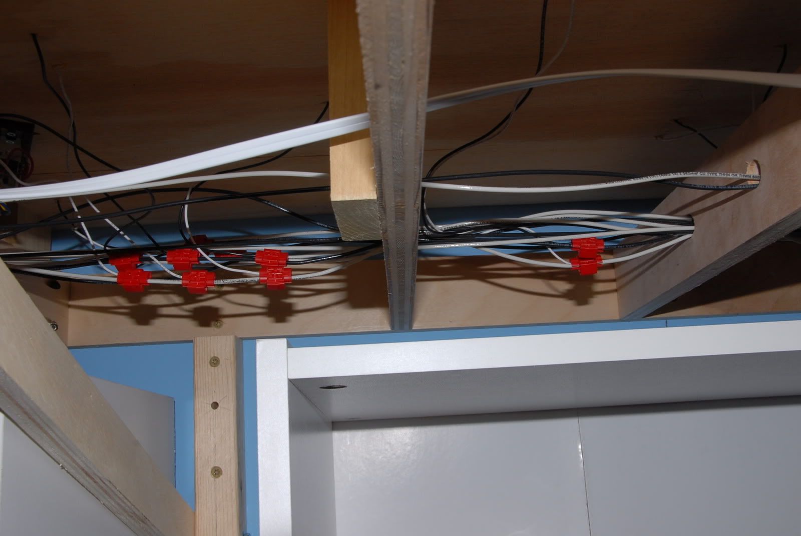
There are 3 sets of wires running along below the layout. Going thru the holes closest to the wall are the 5 pairs of 14AWG main bus wires that feed the 20AWG track feeders. They are connected with the red 3M Scotchlok connectors. The middle set of holes are the wires for 12VDC power for the Digitrax DS64 turnout decoders. The hole nearest to the front edge of the layout is for the Loconet 6 conductor datawire connecting the Digitrax components together.
Here you see two of the DS64s mounted to a hinged board that folds out of the way, wired up and ready to go. The blue and yellow wires not connected are for the future turnout position control panels that will be mounted on the front fascia. They are connected to the turnout machine PL-10 switches.

Here is the same board, held up out of the way so it will not be visible during normal operations. Once the fascia is up it will be totally invisible.

The netbook that I'm using to program the decoders with JMRI Decoder Pro is shown in this final picture. It is hooked up to a Digitrax PR3 which ties it to the Loconet and the programming track. It will also be used to future layout control via JMRI.

So another milestone has been reached. Now is where the next challenge begins, the construction of the helix...
No comments:
Post a Comment